
In this post we’ll review several ways to let users align diagram nodes. The sample code is for WPF, but similar properties and methods exist in MindFusion.Diagramming APIs for other platforms.
Alignment Grid
The alignment grid is used to align nodes coordinates at even intervals during user interactions. To enable alignment, set diagram’s AlignToGrid property to true. Set ShowGrid to show or hide the grid, and GridStyle to toggle its appearance between points and lines. GridOffsetX and GridOffsetY properties let you offset the grid a bit from diagram’s edges:
diagram.ShowGrid = false;
diagram.AlignToGrid = false;
diagram.GridPen = new Pen(Brushes.LightGray, 0.2);
diagram.GridOffsetX = 0;
diagram.GridOffsetY = 0;
diagram.GridStyle = GridStyle.Lines;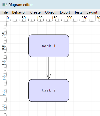
Note that setting items’ coordinates from code does not automatically align them to a grid. Call the AlignPointToGrid method if you need to find aligned coordinates.
Automatic Node align
Set the AutoAlignNodes property to enable alignment guides that let users align moved or resized node to nearby nodes. The guides allow aligning nodes’ borders or center points:
diagram.AutoAlignNodes = true;
diagram.AlignmentGuidePen = new Pen(Brushes.Red, 0.2);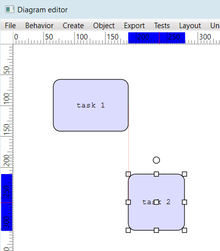
Ruler Alignment Guides
If the Diagram control is placed inside a Ruler, setting ruler’s EnableGuides property will let users align nodes by dragging alignment guide from a ruler’s scale as shown below.
ruler.EnableGuides = true;
ruler.GuideColor = Colors.Red;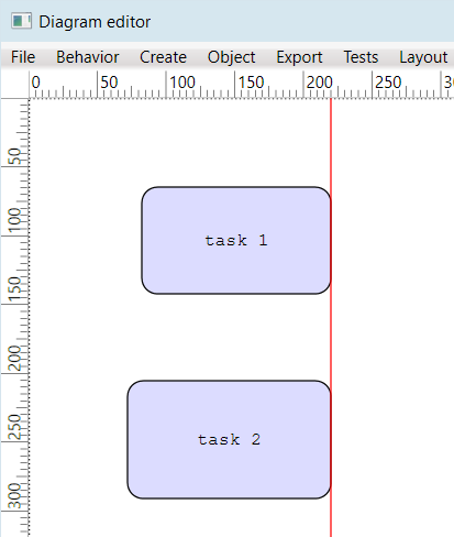
Align from Code
You can implement menu or toolbar commands to align selected nodes by setting nodes’ Bounds property. E.g. following code will align selected nodes to the active selected node (indicated by white adjustment handles vs gray ones). First, let’s create an Align method that uses a callback parameter to abstract what parts of the nodes are aligned:
void Align(
	Func<DiagramNode, DiagramNode, Vector> calcOffset)
{
	var target = diagram.ActiveItem as DiagramNode;
	if (target != null)
	{
		foreach (var node in diagram.Selection.Nodes)
		{
			if (node == target)
				continue;

			var newBounds = node.Bounds;
			newBounds.Offset(
				calcOffset(node, target));
			node.Bounds = newBounds;
		}
	}
}
It allows us implementing different alignment modes like this:
void OnAlignLeft(object sender, EventArgs e)
{
	Align((node, target) => new Vector(
		target.Bounds.Left - node.Bounds.Left, 0));
}

void OnAlignTop(object sender, EventArgs e)
{
	Align((node, target) => new Vector(
		0, target.Bounds.Top - node.Bounds.Top));
}

void OnAlignRight(object sender, EventArgs e)
{
	Align((node, target) => new Vector(
		target.Bounds.Right - node.Bounds.Right, 0));
}

void OnAlignBottom(object sender, EventArgs e)
{
	Align((node, target) => new Vector(
		0, target.Bounds.Bottom - node.Bounds.Bottom));
}

void OnAlignCenterX(object sender, EventArgs e)
{
	Align((node, target) => new Vector(
		target.GetCenter().X - node.GetCenter().X, 0));
}

void OnAlignCenterY(object sender, EventArgs e)
{
	Align((node, target) => new Vector(
		0, target.GetCenter().Y - node.GetCenter().Y));
}
Enjoy!