
In this post we’ll show how to visualize a neural network as a flow diagram. The networks will be loaded from Open Neural Network Exchange (ONNX) file format, with a sample network from the https://github.com/onnx/models collection.
The complete sample project is available here –
https://mindfusion.eu/_samples/NeuralNet.zip
Start by creating a .NET Windows Forms project, in our example we use C# / .NET 6 template. Add the MindFusion.Diagramming Nuget package, and double click the DiagramView and Overview controls from toolbox to add them to the form.
Add the OnnxSharp nuget package, which lets us parse ONNX files. Import the following namespaces into the form’s code-behind:
using Onnx;

using MindFusion.Diagramming;
using MindFusion.Diagramming.Layout;
Parse the ONNX file:
var model = ModelProto.Parser.ParseFromFile(@"inception-v1-12-qdq.onnx");
var graph = model.Graph;
Loop over the network nodes and create respective diagram ones. We’ll use a dictionary to keep track for diagram objects corresponding to ONNX ones. The Onnx.NodeProto class contains many properties, but we’ll show just a few of them in grid format using a TableNode:
var nodeMap = new Dictionary<NodeProto, DiagramNode>();

// create a TableNode for each graph node
foreach (var networkNode in graph.Node)
{
	var diagramNode = diagram.Factory.CreateTableNode(0, 0, 30, 30, 2, 1);
	diagramNode[0, 0].Text = "OpType:";
	diagramNode[1, 0].Text = networkNode.OpType;
	foreach (var attribute in networkNode.Attribute)
	{
		diagramNode.AddRow();
		int r = diagramNode.RowCount - 1;
		diagramNode[0, r].Text = attribute.Name;
		diagramNode[1, r].Text = attribute.Type.ToString();
	}
	diagramNode.ResizeToFitText(false, false);
	diagramNode.Caption = networkNode.Name;
	diagramNode.ConnectionStyle = TableConnectionStyle.Table;

	nodeMap[networkNode] = diagramNode;
}
Style the tables a bit:
diagramNode.Caption = networkNode.Name;
diagramNode.CellFrameStyle = CellFrameStyle.Simple;
diagramNode.Brush = new MindFusion.Drawing.SolidBrush(Color.LightGray);
diagramNode.CaptionBackBrush = new MindFusion.Drawing.SolidBrush(Color.LightSkyBlue);
Find pairs of nodes with matching output -> input identifiers to draw links between them:
// draw links when we find pairs of matching output -> input identifiers
foreach (var networkNode1 in graph.Node)
{
	foreach (var output in networkNode1.Output)
	{
		foreach (var networkNode2 in graph.Node)
		{
			if (networkNode1 == networkNode2)
				continue;

			foreach (var input in networkNode2.Input)
			{
				if (output == input)
				{
					var diagramNode1 = nodeMap[networkNode1];
					var diagramNode2 = nodeMap[networkNode2];
					diagram.Factory.CreateDiagramLink(diagramNode1, diagramNode2);
				}
			}
		}
	}
}
Finally arrange the diagram:
diagram.Arrange(new LayeredLayout { EnforceLinkFlow = true, IgnoreNodeSize = false });
diagram.ResizeToFitItems(5);
The final result should look like –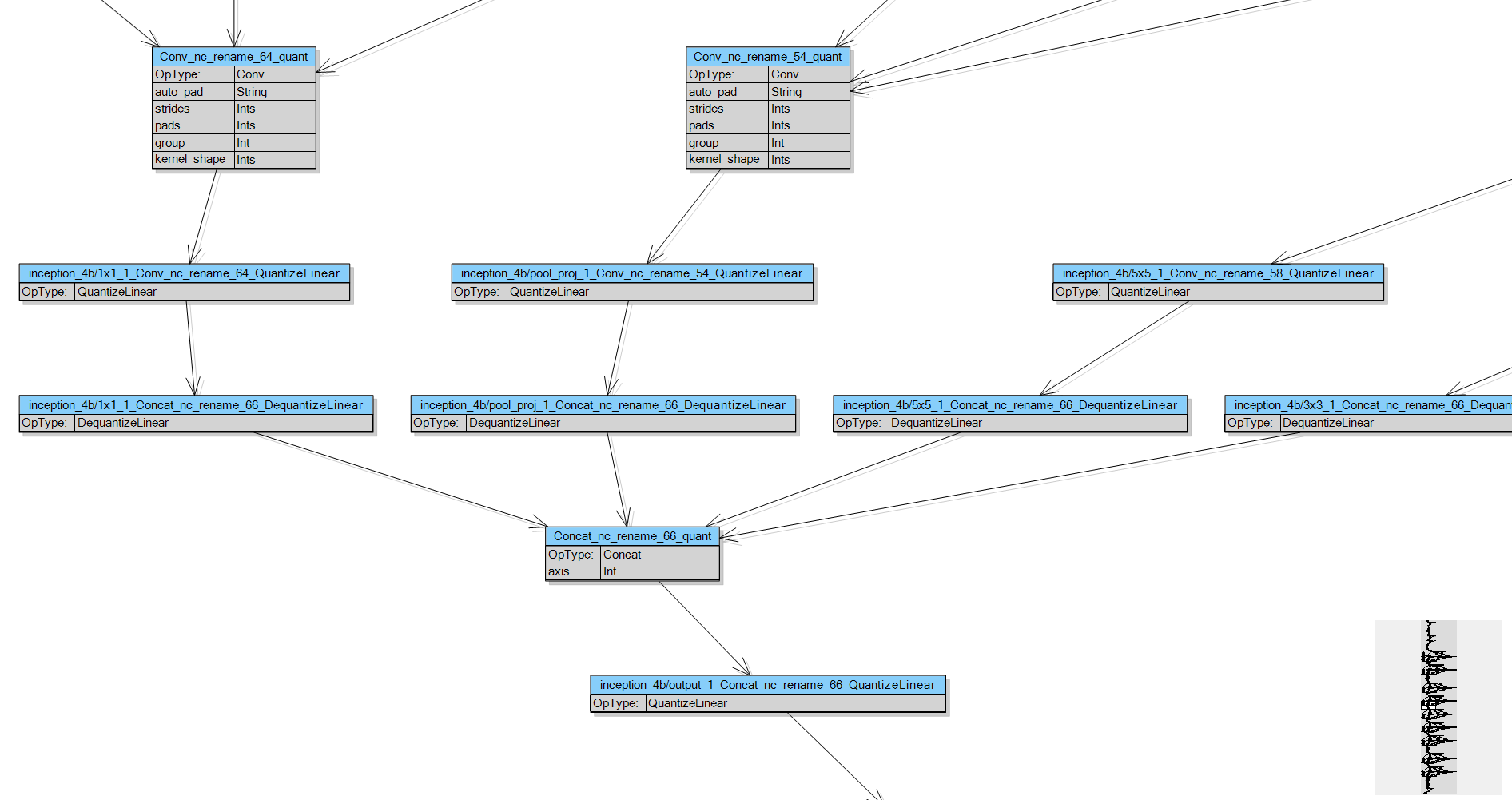
The sample above uses MindFusion’s Windows Forms API. Code for other frameworks will look similar as MindFusion maintains same diagramming model for multiple platforms. You can download the trial version of any MindFusion.Diagramming component from this page.
Enjoy!