
The logic model is a tool that helps managers evaluate the effectiveness of a program. The tool allows the user to list the input, output and outcomes of the process.
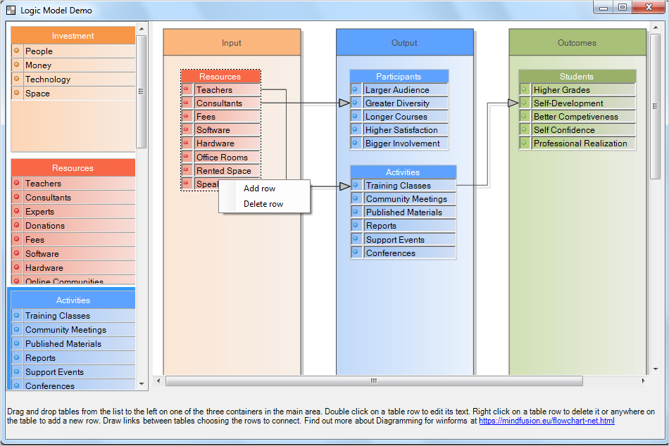
Logic Model Software Demo
In our sample we have used the WinForms Diagram Control to create a sample software that lets users:
- drag and drop tables that represent popular items in each of the three sections of the logic mode: input, output and outcomes;
- edit the tables: add and delete rows, edit the text on rows;
- connect table rows to illustrate the process flow.
I. Project Setup
We create a new project in Visual Studio and name it “LogicModel”. We add references to the following diagramming libraries:
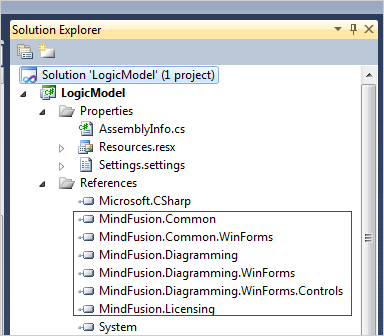
MindFusion Libraries Used by the Logic Model Software
After that we drag and drop the NodeListView control from the Toolbox and set its IconSize property to Size(50,50). This property tells the control how big the items in the NodeListView should be rendered.
nodeListView1.IconSize = new System.Drawing.Size(50, 50)
Then we drag and drop a DiagramView object that creates automatically a Diagram instance that represents the diagram. Here we need to set the AllowDrop and AllowInplaceEdit properties to “true”. This means the diagram can create new nodes from the items in the NodeListView that are dropped onto it. Then it allows the user to edit the nodes e.g. modify the text in the table cells:
this.diagramView1.AllowDrop = true;
this.diagramView1.AllowInplaceEdit = true;
Last but not least we set the Resize mode of the DiagramView to Fill, which means it will occupy all available space when the user changes the size of the application window.
II. The NodeListView
It holds TableNode instances that represent items in the logic model. Let’s look at a simple table. The first table called “Investment”. Here are the first three lines of code for it:
//the table with resources
TableNode tbResources = new TableNode();
tbResources.RedimTable(2, 4);
tbResources.Caption = "Investment";
The RedimTable method changes the number of rows and columns of the TableNode to be the ones specified as arguments. Each of the tables in the logic model has two columns – one for a bullet and one for the label. The count of rows varies.
Then we edit the text that is rendered by this TableNode:
tbResources[1, 0].Text = "People";
tbResources[1, 1].Text = "Money";
tbResources[1, 2].Text = "Technology";
tbResources[1, 3].Text = "Space";
Now is time for some styling. We set the Pen for the table, the pen for the caption and the CaptionBackBrush:
tbResources.Pen = new MindFusion.Drawing.Pen(Color.FromArgb(192, 192, 192));

tbResources.CaptionBrush = new MindFusion.Drawing.SolidBrush(Color.White);
tbResources.CaptionBackBrush = new MindFusion.Drawing.SolidBrush(Color.FromArgb(247, 150, 70));
Then we set the background of the rest of the TableNode:
tbResources.Brush = new LinearGradientBrush(Color.FromArgb(252, 213, 181), Color.FromArgb(248, 234, 223));
Each diagram item has a Tag property. This useful property holds any information you find useful. It is of type Object and you can use it to store data used by your node. In our application we use the Tag property of a TableNode to store the URL to the bullet rendered before each of its labels:
//keep the bullet as a tag
tbResources.Tag = Image.FromFile("../../Resources/orange.png");
//set an orange bullet before each label

for (int i = 0; i < tbResources.Rows.Count; i++)
     {
        tbResources[0, i].Image = Image.FromFile("../../Resources/orange.png");
        //save the row index as a tag for cells with text
        tbResources[1, i].Tag = i;
     }
Then we use the Tag property of the TableNode.Cell objects to store their row index. We will use it later when we handle events.
Finally, let’s not forget to add the new TableNode to the NodeListView:
nodeListView1.AddNode(tbResources);
The other tables are created in a similar way.
III. The Containers
The three rectangles where users drop tables are ContainerNode-s. These are special kinds of DiagramNode -s that can hold other nodes. Once placed into them, the containing nodes move with the container. Containers can resize automatically to fit all items but in our case we will forbid this.
Here is the code that creates the third container – “Outcomes”:
//the last container
ContainerNode cOutcomes = diagram1.Factory.CreateContainerNode(0, 0, 20, 20);
cOutcomes.Tag = 2;
cOutcomes.Caption = "Outcomes";
Note that we use again the Tag property this time to keep the index of the container – first, second or third e.g. 0, 1 or 2. Then we add some styling using the Pen, CaptionBrush, CaptionBackBrush and Brush properties to define the background and border of the container and its caption:
cOutcomes.Pen = new MindFusion.Drawing.Pen(Color.FromArgb(80, 80, 80));
cOutcomes.CaptionBrush = new MindFusion.Drawing.SolidBrush(Color.FromArgb(80, 80, 80));
cOutcomes.CaptionBackBrush = new MindFusion.Drawing.SolidBrush(Color.FromArgb(168, 192, 120));
cOutcomes.Brush = new LinearGradientBrush(Color.FromArgb(209, 224, 180), Color.FromArgb(235, 238, 229));
Then we set some properties that define how the ContainerNode responds to new items being added or removed:
cOutcomes.AllowAddChildren = true;
//do not allow the container to change size or be folded
cOutcomes.AutoGrow = false;
cOutcomes.AutoShrink = false;
cOutcomes.Foldable = false;
We let the container accept new children and do not allow the user to fold, which means to collapse it.
The containers are sized relatively to the client area of the DiagramView:
//resize the containers according to the current size of the diagramView
private void resizeContainers()
  {
    //convert the size of the rectangle from client measure units to diagram units
    RectangleF viewRect = diagramView1.ClientToDoc(diagramView1.ClientRectangle);
   ...
}
First we convert the size of the DiagramView to diagram units calling the ClientToDoc method. Then we need to find the ContainerNode -s of the diagram and arrange them next to each other. When we do this we use the Tag property of each container that tells us which is the order of the container and where we should pace it:
//identify the containers
foreach (DiagramNode node in diagram1.Nodes)
     {
       ContainerNode c = node as ContainerNode;

       if (c != null)
       {
          //get the index that tells us if this is the first, second or third container
          int index = (int)c.Tag;
          //relocate the container rectangle based on its index
          c.Bounds = new RectangleF(viewRect.Left + viewRect.Width * (0.02F + index * 0.34F),
          viewRect.Top + viewRect.Height * 0.02F, viewRect.Width * 0.27F, viewRect.Height * 0.96F);
       }
    }
We call this method each time the DiagramView is resized by handling the ClientSizeChanged event:
//raised when the size of the ClientRectangle has changed.
private void diagramView1_ClientSizeChanged(object sender, EventArgs e)
  {
    //adjust the size of the containeres
     resizeContainers();
     ...
  }
IV. Diagram Events
We handle the NodeCreated diagram event each time the user drops a new node from the NodeListView onto any of the ContainerNode-s:
this.diagram1.NodeCreated += new System.EventHandler(this.diagram1_NodeCreated);
The method that handles the event should do three important things: 1) resize the new TableNode so all text fits into it; 2)assign to each cell its correct Tag (e.g. row index) and 3) find the ContainerNode onto which the TableNode was placed and add it to it. Here is the first part of the method:
//raised when the user has dropped a new TableNode
private void diagram1_NodeCreated(object sender, NodeEventArgs e)
  {
     TableNode tNode = e.Node as TableNode;

    if (tNode != null)
    {
        //adjust the node size
        resizeNode(tNode);
        //arrange the tags for the table cells
        arrangeTags(tNode);

     }
The resizeNode and arrangeTags methods adjust the size of the TableNode and assign to each cell in the second column of the node its row index as a Tag. We won’t list the methods here, you can check them in the source code available for download.
We find the ContainerNode, if any onto which the TableNode was placed by checking if its top left corner is inside the container:
//find out the container onto which the node was dropped, if any
foreach (DiagramNode diagramNode in diagram1.Nodes)
  {
    if (diagramNode.ContainsPoint(e.Node.Bounds.Location))
    {
       ContainerNode container = diagramNode as ContainerNode;
       if (container != null)
       {
         //add the new node to its container
         container.Add(tNode);

         break;
       }
 }
}
If it is within the container we add the node.
V. Context Menu
The context menu is rendered at right mouse click. We handle the CellClicked event of a diagram to show it:
//tracks when the user clicks on a table cell
diagram1.CellClicked += new EventHandler(diagram1_CellClicked);
We also declare a global TableNode.Cell clickedCell variable that keeps track of the clicked cell. We will use the data later:
//keeps the cell the user has clicked on
TableNode.Cell clickedCell = null;
In the diagram1_CellClicked event we check if the right mouse button was clicked and then show a ContextMenuStrip object:
//handles the cellClicked event
void diagram1_CellClicked(object sender, CellEventArgs e)
  {
    //if the user has clicked with the right mouse button
    if(e.MouseButton == MouseButton.Right)
      {
        //we should keep track of the clicked cell
        clickedCell = e.Cell;
        //and show the context menu
        cMenu.Show(Cursor.Position);

       }
  }
We handle the ItemClicked event of the ContextMenuStrip:
if (clickedCell != null)
   {
      TableNode tNode = clickedCell.Table;

      //if the user has selected to add a row
      if (e.ClickedItem.Text.Equals("Add row"))
         {
            //add a row
            tNode.AddRow();
            //assign the image URL kept as a tag to the first cell in the new row
            tNode[0, tNode.Rows.Count - 1].Image =
                 tNode.Tag as Image;
            //type in some dummy text in the text cell
            tNode[1, tNode.Rows.Count - 1].Text = "[edit text]";
        }
..............
}
In the first part of the method we handle the case when the user has chosen to add a new row. The new row is inserted at the end of the table with the AddRow method. We use the Tag property of the TableNode which points to the location of the bullet for this table and we render it to the first cell of the new row.
If the user wants to delete a row we show first a warning message. Here we render the name of the detected row to be deleted. If the user agrees we get the index of the row using its Tag and we remove it from the TableNode:
 else if (e.ClickedItem.Text.Equals("Delete row"))
      {
          cMenu.Close();

          //display a warning, which shows which row is about to be deleted
          string message = "Do you want to delete row " + clickedCell.Text + "?";
          string caption = "Confirm Delete";
          MessageBoxButtons buttons = MessageBoxButtons.YesNo;
          DialogResult result;

          // Displays the MessageBox.
          result = MessageBox.Show(message, caption, buttons);
          //if the user has decided to delete the row
          if (result == System.Windows.Forms.DialogResult.Yes)
            {

             //get the index of the row that is to be deleted
             int rowIndex = (int)clickedCell.Tag;
             tNode.DeleteRow(rowIndex);

           }
...
}
Both actions of delete and insert of a new row require the indices of the table rows to be rearranged and the size of the table to be adjusted. We call:
//adjust the node size
resizeNode(tNode);
//arrange the table tags
arrangeTags(tNode);
VI. Links
Users can draw links between rows of the tables. To achieve this we first change the default Behavior of the DiagramView :
this.diagramView1.Behavior = MindFusion.Diagramming.Behavior.LinkTables;
Then we add some styling for the links:
//styling the links
diagram1.LinkShape = LinkShape.Cascading;
diagram1.LinkCascadeOrientation = MindFusion.Diagramming.Orientation.Horizontal;
diagram1.LinkHeadShape = ArrowHeads.Triangle;
diagram1.LinkHeadShapeSize = 4;
Here we define the shape of the links as “Cascading” and we change the default LinkHeadShape and LinkHeadShapeSize properties. Further styling of the links is done with a Theme and a DiagramLinkStyle:
//create a theme to apply additional link styling
Theme theme = new Theme();
DiagramLinkStyle style = new DiagramLinkStyle();
style.Brush = new MindFusion.Drawing.SolidBrush(Color.FromArgb(192, 192, 192));
style.Stroke = new MindFusion.Drawing.SolidBrush(Color.FromArgb(80, 80, 80));
theme.RegisterStyle(typeof(DiagramLink), style);
diagram1.Theme = theme;
There we specify the Brush for the links and the Stroke. When new links are created we want them to have 3 segments because this looks good. So, we handle the LinkCreated event to specify this:
this.diagram1.LinkCreated += new System.EventHandler(this.diagram1_LinkCreated);

..................

//raised when the user draws a link between two tableNode-s.
private void diagram1_LinkCreated(object sender, LinkEventArgs e)
  {
    //the link should have 3 segments
    e.Link.SegmentCount = 3;
  }
With this our Logic Mode demo application is ready. The complete code for the application with all necessary libraries of the diagramming component is available for free direct download download from here:
Download the Logic Model Demo Application Source Code
About MindFusion.Diagramming for WinForms: A programming component that provides any WinForms application with a full set of features for creating and customizing all types of diagrams, flowcharts, schemes, hierarchies, trees, graphs etc. The control provides numerous ways to save and load a diagram, six auxiliary controls and more than 15 automatic graph layout algorithms. Diagram elements include scrollable tables, container nodes, multi-segment arrows, custom diagram item types and many more. Further details here.
Diagramming for WinForms is a royalty-free component, clients get 12 month upgrade subscription when buying a license. The source code is also available for purchase. Visit the buy page for a list with the current license prices.