Create a musical score writer using MindFusion diagram component.

In this example we’ll show how to use various features of MindFusion.Diagramming API to create a musical score editor:

Custom node types
We’ll create a StaffNode class to represent the staff, and NoteNode class to represent a musical note.

Grouping
NoteNodes will be attached to the StaffNode they were dropped onto (or nearby). If users move the staff around, the notes from the group will follow it.

Custom drawing logic
We’ll show how to draw custom graphics by overriding DrawLocal method of base DiagramNode class.

Using SVG images
We’ll show how to load an SVG image (for the G clef) and draw it as part of staff graphics.

NodeListView control
NodeListView contains prototypical node instances whose clones are added to the diagram using drag-and-drop operations. We’ll add a staff and several notes to the list to let users drag them to the score diagram.

The completed sample project can be downloaded from this link:
ScoreWriter.zip

Let’s start by defining StaffNode class to draw staves in the score diagram, and implement its Draw methods to draw five lines:

public class StaffNode : DiagramNode
{
	public StaffNode()
	{
		var rect = Bounds;
		rect.Width = 200;
		SetBounds(rect, false, false);

		// disable vertical resize
		EnabledHandles =
			AdjustmentHandles.ResizeMiddleLeft |
			AdjustmentHandles.Move |
			AdjustmentHandles.ResizeMiddleRight;
	}

	public StaffNode(StaffNode prototype) : base(prototype)
	{
	}

	public override void DrawLocal(IGraphics graphics, RenderOptions options)
	{
		base.DrawLocal(graphics, options);

		for (int i = 0; i < 5; i++)
		{
			float y = i * Bounds.Height / 4;
			using (var pen = EffectivePen.CreateGdiPen())
				graphics.DrawLine(pen, 0, y, Bounds.Width, y);
		}
	}

	public override void DrawShadowLocal(IGraphics graphics, RenderOptions options)
	{
	}
}

Next, load an SVG drawing representing G clef and draw it at appropriate position. We’ll also override GetRepaintRect method to accommodate for parts of the clef that are drawn outside the staff’s boundaries:

static SvgContent gClef;

static StaffNode()
{
	gClef = new SvgContent();
	gClef.Parse("GClef.svg");
}

public override void DrawLocal(IGraphics graphics, RenderOptions options)
{
	// ...

	var rect = GetLocalBounds();
	rect.Inflate(0, 8);
	rect.X = 2;
	rect.Width = 14;
	gClef.Draw(graphics, rect);
}

public override RectangleF GetRepaintRect(bool includeConnected)
{
	var rect = base.GetRepaintRect(includeConnected);
	rect.Inflate(0, 8);
	return rect;
}

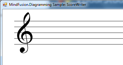
Create an initial StaffNode instance from Form.Load event:

var initialStaff = new StaffNode();
initialStaff.Move(10, 10);
diagram.Nodes.Add(initialStaff);

If you run the project now, you should see the following diagram:
score writer diagram in c#

Next, define the Duration enumeration and NoteNode class to represent musical notes of various durations:

enum Duration
{
	Whole,
	Half,
	Quarter,
	Eighth,
	Sixteenth
}

class NoteNode : DiagramNode
{
	public NoteNode()
	{
		Bounds = new RectangleF(0, 0, 6, 6);
		Duration = Duration.Whole;
	}

	public NoteNode(Duration duration)
	{
		Bounds = new RectangleF(0, 0, 6, 6);
		Duration = duration;
	}

	public Duration Duration { get; set; }

	int position = 0;
}

Implement NoteNode.Draw methods as follows:

public override void DrawLocal(IGraphics graphics, RenderOptions options)
{
	base.DrawLocal(graphics, options);

	var cx = Bounds.Width / 2;
	var cy = Bounds.Height / 2;

	var gs = graphics.Save();
	graphics.TranslateTransform(cx, cy);
	graphics.RotateTransform(-10);
	graphics.TranslateTransform(-cx, -cy);

	var bounds = GetLocalBounds();
	bounds.Inflate(0, -bounds.Width / 10);
	var path = new GraphicsPath();
	path.AddEllipse(bounds);

	if (Duration == Duration.Whole || Duration == Duration.Half)
	{
		bounds.Inflate(-bounds.Width / 8, -bounds.Width / 6);
		path.AddEllipse(bounds);
	}
	graphics.FillPath(Brushes.Black, path);

	graphics.Restore(gs);

	if (position < -1 || position > 8)
	{
		// draw ledger lines if above or below staff
		var pen = EffectivePen.CreateGdiPen();
		var staff = (StaffNode)MasterGroup.MainItem;
		var yoff = staff.Bounds.Y - Bounds.Y;
		int i1 = position < -1 ? position : 9;
		int i2 = position < -1 ? -2 : position;
		for (int i = i1; i <= i2; i++)
		{
			if (i % 2 != 0)
				continue;
			var y = yoff + i * staff.Bounds.Height / 8;
			graphics.DrawLine(pen, -2, y, Bounds.Width + 2, y);
		}
		pen.Dispose();
	}

	if (Duration != Duration.Whole)
	{
		// draw stem
		float x = Bounds.Width;
		float y = Bounds.Height / 2;
		var pen = new System.Drawing.Pen(Color.Black, 0.5f);
		graphics.DrawLine(pen,
				            x - pen.Width / 2, y,
				            x - pen.Width / 2, y - Bounds.Height * 2);
		pen.Dispose();
	}

	if (Duration == Duration.Eighth || Duration == Duration.Sixteenth)
	{
		DrawFlag(graphics,
				    bounds.Width,
				    bounds.Height / 2 - bounds.Height * 2,
				    bounds.Width + 1,
				    bounds.Height);
	}

	if (Duration == Duration.Sixteenth)
	{
		DrawFlag(graphics,
				    bounds.Width,
				    bounds.Height - bounds.Height * 2,
				    bounds.Width + 1,
				    bounds.Height);
	}
}

void DrawFlag(IGraphics graphics, float x, float y, float w, float h)
{
	float sh = h / 2;
	float sw = w / 3;

	var pen = new System.Drawing.Pen(Color.Black, 0.5f);
	x -= pen.Width / 2;
	graphics.DrawBezier(pen,
			            x, y,
			            x, y + sh,
			            x + sw * 1.2f, y + 2 * sh,
			            x + sw, y + 3 * sh);
	pen.Dispose();
}

public override void DrawShadowLocal(IGraphics graphics, RenderOptions options)
{
}

public override RectangleF GetRepaintRect(bool includeConnected)
{
	var r = Bounds;
	r.Y -= r.Height * 2;
	r.Height *= 3;
	r.Width *= 2;
	return r;
}

Now, drag a NodeListView to the form and populate it from Load handler:

nodeListView.AddNode(new StaffNode());

nodeListView.DefaultNodeSize = new SizeF(6, 6);
nodeListView.AddNode(new NoteNode(Duration.Whole));
nodeListView.AddNode(new NoteNode(Duration.Half));
nodeListView.AddNode(new NoteNode(Duration.Quarter));
nodeListView.AddNode(new NoteNode(Duration.Eighth));
nodeListView.AddNode(new NoteNode(Duration.Sixteenth));

Drag and drop will not work just yet. First, we must enable the DiagramView.AllowDrop property to accept drag-and-drop events. Next, the custom classes must implement a copy constructor and serialization methods to be able to instantiate them through OLE drag events:

public NoteNode(NoteNode prototype) : base(prototype)
{
	Duration = prototype.Duration;
}

protected override void SaveTo(System.IO.BinaryWriter writer, PersistContext context)
{
	base.SaveTo(writer, context);
	context.Writer.Write((int)Duration);
}

protected override void LoadFrom(System.IO.BinaryReader reader, PersistContext context)
{
	base.LoadFrom(reader, context);
	Duration = (Duration)context.Reader.ReadInt32();
}

As a final touch for this example, let’s implement aligning notes to staves’ lines and spaces. First lets declare a helper method that returns the nearest StaffNode at specified location in diagram:

static class DiagramExtensions
{
	static public StaffNode NearestStaff(this Diagram diagram, PointF point)
	{
		var staves = diagram.Nodes.OfType();

		StaffNode nearest = null;
		float minDist = float.MaxValue;

		foreach (var staff in staves)
		{
			if (staff.ContainsPoint(point))
				return staff;

			var borderPoint = staff.GetNearestBorderPoint(point);
			var dist = Utilities.Distance(borderPoint, point);
			if (dist < minDist)
			{
				minDist = dist;
				nearest = staff;
			}
		}

		return minDist < 20 ? nearest : null;
	}
}

Next, implement StaffNode.Align method that aligns its argument to a line or space in the staff:

public PointF Align(PointF point, out int position)
{
	// align to pitch line/space

	float h = Bounds.Height / 8;
	float offset = point.Y - Bounds.Y;
	position = (int)Math.Round(offset / h);
	offset = (float)Math.Round(offset / h) * h;
	point.Y = Bounds.Y + offset;
	return point;
}

Add NoteNode.AlignToStaff method that will find nearest StaffNode and align the note’s position to the staff.

public StaffNode AlignToStaff()
{
	position = 0;

	var staff = Parent.NearestStaff(GetCenter());
	if (staff == null)
		return null;

	var alignedPoint = staff.Align(GetCenter(), out position);
	alignedPoint.X -= Bounds.Width / 2;
	alignedPoint.Y -= Bounds.Height / 2;
	Move(alignedPoint.X, alignedPoint.Y);

	return staff;
}

We can align notes after drag-and-drop from NodeListView by handling diagram’s NodeCreated event. We’ll use the same handler to attach notes to that staff, so that if users move a StaffNode, its attached NoteNodes will follow.

private void OnNodeCreated(object sender, NodeEventArgs e)
{
	var note = e.Node as NoteNode;
	if (note != null)
	{
		var staff = note.AlignToStaff();
		if (staff != null)
			note.AttachTo(staff, AttachToNode.TopLeft);

		note.HandlesStyle = HandlesStyle.MoveOnly;
	}
}

Finally, override NoteNode.CompleteModify to align notes after user moves them to a different position on the staff or to another staff in the score:

protected override void CompleteModify(PointF end, InteractionState ist)
{
	base.CompleteModify(end, ist);

	var staff = AlignToStaff();
	if (staff != null)
		AttachTo(staff, AttachToNode.TopLeft);
	else
	{
		Detach();
	}
}

Let’s run the project and compose some music 🙂
.net diagram control

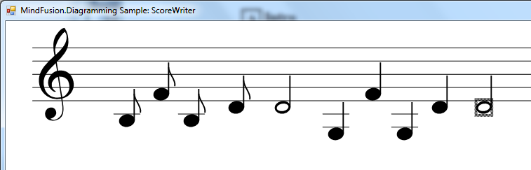
A fully-featured scorewriter software would also allow for drawing rest, sharp and flat symbols, C and F clefs, and some other musical notation features, but these are left as exercise to the reader 😉

The code above uses MindFusion’s .NET API and can be used with Windows Forms, WPF, Silverlight and ASP.NET diagramming components. The Java API for Android and desktop Swing application will look similar, with setter method calls instead of property assignments.

You can download the trial version of any MindFusion.Diagramming component from this page.

Enjoy!

WPF Diagram Control, V3.3.1 and WinForms Diagram Control, V6.3.3

MindFusion is pleased to announce the new releases of two of its popular flowchart control: Diagramming for WinForms, V6.3.3 and Diagramming for WPF, V3.3.1. Both releases have similar new features, which are listed below:

Resize table columns and rows
Columns and rows of a TableNode can now be resized interactively if its AllowResizeColumns or AllowResizeRows properties are enabled. In order to resize, move the mouse pointer to the border line on column’s right side or row’s bottom side until it shows resize cursor and start dragging. The control raises TableColumnResizing and TableRowResizing events to let you validate new size or prevent resizing some elements. The TableColumnResized and TableRowResized events are raised after the operation completes.

Barcode nodes
The BarcodeNode class displays EAN, UPC or QR barcodes as node’s content. In-place edit operations let users enter new numeric codes for 1D codes or text strings for QR codes. The barcode format is specified via the Format property, the encoded number or text is set via Content, and color of 1D bars / 2D modules via BarColor.

Barcode diagram nodes

Barcode diagram nodes

New Features in Diagramming for WPF, V3.3.1

ShapeDesigner improvements

  • The ShapeDesigner control supports undo. Call its Undo or Redo methods to respectively undo or redo a change done to the designed shape.
  • ZoomFactor property added to ShapeDesigner. It also supports interactive zoom in/out via mouse wheel.
  • The SelectedElement property exposes the graphic element currently selected in ShapeDesigner canvas. You can bind to its stroke and brush properties to create alternative user interface for editing element attributes.

Miscellaneous

  • NodeConstraints.KeepInsideDiagram prevents a node from leaving diagram boundaries during user interaction (the older RestrictItemsToBounds property does not stop nodes from leaving diagram area but returns them to original position if dropped outside).
  • dashed selection frames are now drawn in two colors and should be visible on both the default white background and custom darker backgrounds. You can change the second dash color via HandlesVisualStyle.DashBackground property.
  • set the WhileModifying flag in RoutingOptions.TriggerRerouting to reroute links while users drag their end points.
  • custom connection point classes can now override ConnectionPoint.NearestAnchorPoint to implement custom anchor point selection logic; the method is now also called at the beginning of interactive link creation.

New in Diagramming for WinForms, V6.3.3

Miscellaneous

  • the component now selects better end points for auto-routed links when using WhileCreating and WhileModifying routing modes;
  • custom connection point classes can now override ConnectionPoint.NearestAnchorPoint to implement custom anchor point selection logic; the method is now also called at the beginning of interactive link creation.
  • NodeConstraints.KeepInsideDiagram prevents a node from leaving diagram boundaries during user interaction (the older RestrictItemsToBounds property does not stop nodes from leaving diagram area but returns them to original position if dropped outside).
  • SvgNode supports SVG images with vector-effect=’non-scaling-stroke’ stroke attributes.
  • improved default Pen for dash-frame selection handles style. Dashed frames should now be visible on both the default white background and custom darker backgrounds.
  • ZoomControl can now be used with other components by MindFusion and has been moved to MindFusion.Common.WinForms assembly and namespace.

You are welcome to download the trial version for each control from the following links:

Diagramming for WinForms, V6.3.3 Trial Version Download

Diagramming for WPF, V3.3.1 Trial Version Download

If you have questions or run into problems using the components you can use the Diagramming components forum, the help desk or write us at support@mindfusion.eu. Our support team will be pleased to help you.

About MindFusion.Diagramming for WinForms: A programming component that provides any WinForms application with a full set of features for creating and customizing all types of diagrams, flowcharts, schemes, hierarchies, trees, graphs etc. The control provides numerous ways to save and load a diagram, six auxiliary controls and more than 10 automatic graph layout algorithms. Diagram elements include scrollable tables, container nodes, multi-segment arrows, custom diagram item types and many more. Further details here.

Diagramming for WinForms is a royalty-free component, clients get 12 month upgrade subscription when buying a license. The source code is also available for purchase. Visit the buy page for a list with the current license prices.

About MindFusion.Diagramming for Wpf: Designed and developed to be easy to integrate, use, and customize, this native WPF flowchart component places at your disposal every single feature you would ever need to create diagrams, graphs, schemes, org charts, DB relationships, genealogy trees, class hierarchies and many more. Its long list of style options gives you complete control over the appearance of the diagram. With a set of eight automatic layouts you are sure to find the arrangement that suits perfectly your WPF application.

The diagram control boasts a long list of events, properties and methods for user interaction, item creation, data input and output. You can read the full features list here. The online demo shows samples that demonstrate various capabilities of the control. The licensing scheme and prices are uploaded at the buy page. Source code is also available.

Combine layout algorithms

Apply FractalLayout and SpringLayout to generate a tag cloud

In a series of posts we’ll explore ways to combine graph layout algorithms for various purposes, such as improving layout speed or achieving specific layout constraints.

In this topic we’ll show how to create a tag cloud using FractalLayout and SpringLayout algorithms from MindFusion diagramming API. You can download the complete project here:

TagCloud.zip

The sample code will show several features of the Diagram control:

  • FractalLayout
  • SpringLayout
  • custom node placement
  • text-only nodes

We assume words frequencies are already counted and listed as “word: frequency” entries in a sorted file. The example uses tags extracted from the contents of Wikipedia’s Tag cloud page. Let’s start by parsing the file and creating a node for each word. We’ll assign the word frequency to the Weight property of nodes for future reference. Weight is also used by some layout algorithms (such as TreeMapLayout for creating tree maps) that could visually represent word frequencies as well:

RectangleF defaultBounds = new RectangleF(0, 0, 10, 20);
ShapeNode root;
		
private void MainForm_Load(object sender, EventArgs e)
{
	// read the tags file
	var reader = new StreamReader("words.txt");
	string line;
	while ((line = reader.ReadLine()) != null)
	{
		// each line contains "word: frequency" entries
		var parts = line.Split(new[] { ':' });
		var word = parts[0];
		var frequency = int.Parse(parts[1]);

		// create a diagram node for each word in the file
		var node = diagram.Factory.CreateShapeNode(defaultBounds);
		node.Weight = frequency;
		node.Text = word;

		// set font size corresponding to frequency
		node.Font = new Font(
			"Arial",
			8 + (float)Math.Log(node.Weight, 1.15),
			GraphicsUnit.Point);

		// resize the node to fit text
		var size = TextRenderer.MeasureText(node.Text, node.Font);
		node.Resize(
			2 + (float)MeasureUnit.Pixel.Convert(size.Width, diagram.MeasureUnit, null),
			2 + (float)MeasureUnit.Pixel.Convert(size.Height, diagram.MeasureUnit, null));

		// show only text, hide geometry
		node.Transparent = true;
	}
}

Next, let’s build a tree that will distribute largest nodes roughly uniformly when arranged by FractalLayout, where larger parent nodes are circled by their smaller child nodes:

while ((line = reader.ReadLine()) != null)
{
	// ...
	if (diagram.Nodes.Count == 1)
	{
		// save reference to the first node
		root = node;
	}
	else
	{
		// build a tree where each node has up to six children
		diagram.Factory.CreateDiagramLink(
			diagram.Nodes[diagram.Nodes.Count / 6],
			node);
	}
}

// use FractalLayout for initial placement. if the file entries are sorted, each circular
// branch will contain larger parent node centered between its smaller children
new FractalLayout().Arrange(diagram);

If you run the application now, you should see the following layout:

a tree arranged using fractal layout

FractalLayout allocates some space for links, and we’ll reclaim it by deleting the links and compressing the initial layout of nodes:

// remove the links
while (diagram.Links.Count > 0)
	diagram.Links.RemoveAt(diagram.Links.Count - 1);

// pull all nodes towards the root to eliminate empty space that was occupied by links
var center = root.GetCenter();
foreach (var node in diagram.Nodes.Where(n => n != root))
{
	var relativePos = new Vector(center, node.GetCenter());
	var newPos = center + relativePos / 10;
	node.Move(
		newPos.X - node.Bounds.Width / 2,
		newPos.Y - node.Bounds.Height / 2);
}

Now apply SpringLayout to make distances between closely placed nodes more uniform, running only a few iterations to complete faster:

// run SpringLayout to distribute nodes more uniformly
var sl = new SpringLayout();
sl.Randomize = false;
sl.SplitGraph = false;
sl.NodeDistance = 3;
sl.IterationCount = 40;
sl.Arrange(diagram);

Run the following method to remove any overlaps remaining after SpringLayout. RemoveOverlaps works by starting from specified node and offsetting any nodes that overlap it, continuing by spiraling away while processing other nodes. This method could also be useful in an interactive application if you want to disperse overlapping nodes introduced by the user when they move a node:

void RemoveOverlaps(DiagramNode modifiedNode, float minDist)
{
	var queue = new Queue();
	queue.Enqueue(modifiedNode);

	while (queue.Count > 0)
	{
		var node = queue.Dequeue();
		var nodeCenter = node.GetCenter();
		var overlaps = FindOverlaps(node, minDist);
		foreach (var overlap in overlaps)
		{
			var ovrCenter = overlap.GetCenter();
			var ovrBounds = overlap.Bounds;
			var dx = ovrCenter.X - nodeCenter.X;
			var dy = ovrCenter.Y - nodeCenter.Y;
			if (Math.Abs(dx) > Math.Abs(dy))
			{
				// offset horizontally
				if (dx < 0)
					ovrBounds.X = node.Bounds.Left - ovrBounds.Width - minDist;
				else
					ovrBounds.X = node.Bounds.Right + minDist;
			}
			else
			{
				// offset vertically
				if (dy < 0)
					ovrBounds.Y = node.Bounds.Top - ovrBounds.Height - minDist;
				else
					ovrBounds.Y = node.Bounds.Bottom + minDist;
			}

			// shifting the node might introduce new overlaps, continue processing
			overlap.Bounds = ovrBounds;
			queue.Enqueue(overlap);
		}
	}
}

List FindOverlaps(DiagramNode modifiedNode, float minDist)
{
	var bounds = modifiedNode.Bounds;
	bounds.Inflate(minDist - 1, minDist - 1);

	var overlaps = new List();
	foreach (var node in diagram.Nodes)
	{
		if (modifiedNode == node)
			continue;
		if (bounds.IntersectsWith(node.Bounds))
			overlaps.Add(node);
	}
	return overlaps;
} 

Finally run a few more iterations of SpringLayout to equalize distances again and zoom the diagram to show the whole tag cloud:

// remove any remaining overlaps
RemoveOverlaps(root, 0.1f);
sl.Arrange(diagram);

// show everything inside view
diagram.ResizeToFitItems(5);
diagramView.ZoomToFit();

If you run the application now, you should see the following image:

tag cloud generated using MindFusion diagram control

The code above uses MindFusion’s .NET API and can be used with Windows Forms, WPF, Silverlight and ASP.NET diagramming components. The Java API for Android and desktop Swing application will look similar, with setter method calls instead of property assignments.

You can download the trial version of any MindFusion.Diagramming component from this page.

Enjoy!

Create a Dialogue Editor using MindFusion Diagram

In this post we’ll demonstrate how to create a graphical interface for editing dialogues using MindFusion diagramming API. The sample could be used as a module in different kinds of applications, such as software for creating and conducting surveys, editing interactive voice response systems, designing NPC dialogues in game development tools. You can download the complete project here:

DialogueEditor.zip

The sample code will show several features of Diagram control:

  • TableNode API
  • in-place edit
  • work with groups
  • graph traversal

Questions or IVR messages and their possible answers / responses will be displayed respectively in caption area and cells of TableNode objects. Helper nodes at table bottom will let users add or remove rows. DiagramLink objects connecting table rows to other tables will define the dialogue flow, i.e. what next question / message to display after user selects option from current message.

Let’s start by creating a new .NET Windows Forms project. If you have installed MindFusion diagram control and selected toolbox integration from setup wizard screen, you should now see a Diagram component and DiagramView control in the toolbox. If they are not available, right click and select Choose Items, navigate to installation folder and select the mindfusion.diagramming and mindfusion.diagramming.winforms assemblies. Now drag a Diagram component to the form, and set its name to “diagram”. This automatically adds a diagramming.dll reference to the project. Drag a DiagramView (which add diagramming.winforms reference) and name it diagramView. Set its Diagram property to “diagram”, selecting it from the drop-down in property grid.

We will allow creation only of tables and links, so let’s set DiagramView.Behavior property to LinkTables. Now if users draw on the diagram canvas, the component will create TableNode if the mouse pointer is over unoccupied part of the diagram, or a DiagramLink if the mouse points a table. If we wanted to support more type of nodes, we could add their prototypes to a NodeListView instance and let users create new instances via drag-and-drop.

Add the following fields and constructor code to set up appearance and behavior of diagram elements.

public MainForm()
{
	InitializeComponent();

	// set up initial table appearance
	diagram.TableNodeStyle.Brush = new MindFusion.Drawing.SolidBrush(Color.LightGray);
	diagram.TableRowCount = 1;
	diagram.TableColumnCount = 1;
	diagram.TableCaption = "question";
	diagram.NodeEffects.Add(new GlassEffect());

	// highlight a row when clicked
	diagram.AutoHighlightRows = true;

	// find link routes automatically
	diagram.RouteLinks = true;

	// allow edit texts by double click
	diagramView.AllowInplaceEdit = true;

	// row anchor points
	rightOutput = new AnchorPattern("Right");
	rightOutput.Points.Add(new AnchorPoint(100, 50, false, true));

	// table anchor points
	input = new AnchorPattern("Input");
	input.Points.Add(new AnchorPoint(50, 0, true, false));
	input.Points.Add(new AnchorPoint(50, 100, true, true));
}

AnchorPattern rightOutput;
AnchorPattern input;

Select the diagram component in form editor and double click its NodeCreated event to add event handler. NodeCreated is raised when the user draws a new node. Add following code to associate a question / IVR message with the table, and initialize some default texts. The BeginEdit method automatically opens in-place editor to let user edit caption text immediately after drawing. We also create + and – ShapeNodes that will act as button widgets attached to the table’s bottom-right corner.

private void OnNodeCreated(object sender, MindFusion.Diagramming.NodeEventArgs e)
{
	var table = e.Node as TableNode;
	if (table != null)
	{
		int tableId = (1 + diagram.Nodes.Count / 3);
		table.Id = tableId;
		table.RowAnchorPattern = rightOutput;
		table.AnchorPattern = input;
		table.ConnectionStyle = TableConnectionStyle.Both;
		table[0, 0].Text = "option 1";
		table.Caption = "question " + tableId;
		diagramView.BeginEdit(table);

		// create + button for adding new rows
		var r = table.Bounds;
		var p = new PointF(r.Right - 14, r.Bottom - 8);
		var s = new SizeF(6, 6);
		var plus = diagram.Factory.CreateShapeNode(p, s, Shapes.Cross);
		plus.Brush = new MindFusion.Drawing.SolidBrush(Color.Green);
		plus.AttachTo(table, AttachToNode.BottomRight);
		plus.Tag = "+";

		// create - button for deleting selected row
		p.X += 7;
		p.Y += 2;
		s.Height -= 4;
		var minus = diagram.Factory.CreateShapeNode(p, s, Shapes.Rectangle);
		minus.Brush = new MindFusion.Drawing.SolidBrush(Color.Red);
		minus.AttachTo(table, AttachToNode.BottomRight);
		minus.Tag = "-";

		plus.Locked = minus.Locked = true;
		table.SubordinateGroup.AutoDeleteItems = true;
	}
}

Now add a NodeClicked handler that adds or deletes rows. If the + button is clicked, the code inserts a new row before current highlighted row. If the – button is clicked, the handler deletes current highlighted row.

private void OnNodeClicked(object sender, NodeEventArgs e)
{
	if ("+".Equals(e.Node.Tag))
	{
		var table = (TableNode)e.Node.MasterGroup.MainItem;
		if (table.HighlightedRow == -1)
			table.RowCount++;
		else
			table.InsertRow(table.HighlightedRow);
	}

	if ("-".Equals(e.Node.Tag))
	{
		var table = (TableNode)e.Node.MasterGroup.MainItem;
		if (table.HighlightedRow != -1)
			table.DeleteRow(table.HighlightedRow);
	}
}

Finally, lets create export function that will traverse the dialogue graph and export it to a custom-format XML file, which could then be passed on to a system processing the dialogues, such as IVR service.

private void btnExport_Click(object sender, EventArgs e)
{
	var fileDlg = new SaveFileDialog();
	if (fileDlg.ShowDialog() == DialogResult.OK)
	{
		var doc = new XmlDocument();
		var root = doc.CreateElement("Dialogue");
		doc.AppendChild(root);

		foreach (var node in diagram.Nodes)
		{
			var table = node as TableNode;
			if (table != null)
			{
				var questionElement = doc.CreateElement("Question");
				root.AppendChild(questionElement);

				int id = (int)table.Id;
				questionElement.SetAttribute("Id", table.Id.ToString());
				questionElement.SetAttribute("Text", table.Caption);

				for (int r = 0; r < table.Rows.Count; r++)
				{
					string answer = table[0, r].Text;
					var answerElement = doc.CreateElement("Answer");
					questionElement.AppendChild(answerElement);
					answerElement.SetAttribute("Text", answer);
					if (table.Rows[r].OutgoingLinks.Count > 0)
					{
						var link = table.Rows[r].OutgoingLinks[0];
						var nextQuestion = (TableNode)link.Destination;
						answerElement.SetAttribute("Text", answer);
						answerElement.SetAttribute("NextId", nextQuestion.Id.ToString());
					}
				}
			}
		}

		doc.Save(fileDlg.FileName);
	}
}

If you run the application now and draw several tables and links, you should see a similar screen:

dialogue editor created with mindfusion diagram control for .NET

The code above uses MindFusion’s .NET API and can be used with Windows Forms, WPF, Silverlight and ASP.NET diagramming components. The Java API for Android and desktop Swing application will look similar, with setter method calls instead of property assignments.

You can download the trial version of any MindFusion.Diagramming component from this page.

Enjoy!

Visualize graph algorithms using MindFusion Diagram component

In this post we’ll explore visualization of graph processing algorithms using MindFusion.Diagramming API. The sample Visual Studio project will show animated depth-first and breadth-first search algorithms for graph traversal, but same approach can be applied for visualizing processes in any systems representable as graph data structures, such as message transmission in networks, progress of tasks in workflows, and so on. You can download the complete project here:

GraphSearch.zip

The code will show several techniques you might also find useful in other contexts:

  • build diagram programmatically from model data
  • use styles to temporarily apply several appearance attributes as a single unit
  • synchronize diagram with data coming from a worker thread

Let’s start by creating our (very simple) model classes, Graph and Vertex in this case, where connections in the graph will be stored using standard adjacency lists representation:

class Graph
{
	public List Vertices = new List();
}

class Vertex
{
	public List Neighbors = new List();
	public bool Visited;
	public int Index;
	public int SearchOrder;
}

Next, create a method that builds a diagram from the model objects. The mappings will be saved in a dictionary for later access.

private Dictionary<vertex, shapenode=""> nodes;
readonly RectangleF defaultSize = new RectangleF(0, 0, 10, 10);

///
/// Create diagram elements from graph with adjacency lists representation
/// 
void DiagramFromGraph(Graph g)
{
	diagram.ClearAll();

	// map graph vertices to diagram nodes
	nodes = new Dictionary<vertex, shapenode="">();

	// create a node for each vertex
	foreach (var v in g.Vertices)
	{
		var node = diagram.Factory.CreateShapeNode(defaultSize);
		node.Tag = v;
		nodes[v] = node;
	}

	// create links for adjacencies
	foreach (var v1 in g.Vertices)
	{
		foreach (var v2 in v1.Neighbors)
		{
			// only in one direction
			if (v1.Index < v2.Index)
				diagram.Factory.CreateDiagramLink(nodes[v1], nodes[v2]);
		}
	}

	// arrange the nodes
	new AnnealLayout { Randomize = false }.Arrange(diagram);

	// search starts from selected node
	diagram.Nodes[0].Selected = true;
}
</vertex,></vertex,>

Now create a sample graph and its corresponding drawing which we’ll use to show search progress:

void OnFormLoad(object sender, EventArgs e)
{
	// create sample graph to traverse
	var graph = new Graph();
	graph.GenerateRandom(20, 25);
	DiagramFromGraph(graph);
}

public void GenerateRandom(int v, int e)
{
    var rnd = new Random(42);
    for (int i = 0; i < v; i++)
        Vertices.Add(new Vertex { Index = i});
    int c = 0;
    while (e > 0)
    {
        var v1 = Vertices[c];
        var v2 = Vertices[rnd.Next(v)];
        if (v1 == v2 || v1.Neighbors.Contains(v2))
            continue;
        v1.Neighbors.Add(v2);
        v2.Neighbors.Add(v1);
        c = (c + 1) % v;
        e--;
    }
}

Add two styles we’ll use to show search progress. The first one is for vertices visited by the search algorithm, and the second one is applied temporarily when the algorithm back-tracks:

readonly ShapeNodeStyle visitedNodeStyle = new ShapeNodeStyle
   	{
   		Brush = new MindFusion.Drawing.SolidBrush(Color.Green)
   	};

readonly ShapeNodeStyle backtrackNodeStyle = new ShapeNodeStyle
	{
		Brush = new MindFusion.Drawing.SolidBrush(Color.DarkGreen),
		Stroke = new MindFusion.Drawing.SolidBrush(Color.Red),
		StrokeThickness = 1 // mm
	};

We’ll invoke the following methods from the search algorithm threads to show which vertices have just been processed:

void ShowProgress(Vertex v)
{
	// invoke in UI thread
	diagramView.Invoke(new System.Action(() =>
	{
		// update node style
		var node = nodes[v];
		node.Text = v.SearchOrder.ToString();
		node.Style = visitedNodeStyle;

		if (backtrackNode != null)
			backtrackNode.Style = visitedNodeStyle;
		backtrackNode = null;
	}));
	Thread.Sleep(animationDelay);
}

void ShowBacktrack(Vertex v)
{
	// invoke in UI thread
	diagramView.Invoke(new System.Action(() =>
	{
		if (backtrackNode != null)
			backtrackNode.Style = visitedNodeStyle;

		// update node style
		var node = nodes[v];
		node.Style = backtrackNodeStyle;
		backtrackNode = node;
	}));
	Thread.Sleep(animationDelay);
}

DiagramNode backtrackNode;
int animationDelay = 1000;

We now have everything ready for showing animated progress of graph algorithms. Add a form button that will run a sample depth-first search, add a click event handler called OnDepthFirstSearch, and handle it like this:

void OnDepthFirstSearch(object sender, EventArgs e)
{
	// do not search if there's no node selected
	var startNode = diagram.ActiveItem as DiagramNode;
	if (startNode == null)
		return;

	// search buttons disabled while current search thread runs
	btnDFS.Enabled = btnBFS.Enabled = false;

	// init data structures for new search
	ResetSearch();

	// get vertex corresponding to selected node
	var startVertex = (Vertex) startNode.Tag;

	// start depth-first search in a new thread
	currentSearch = new Thread(() =>
		DepthFirstSearch(startVertex, 0));
	currentSearch.Start();
}

int DepthFirstSearch(Vertex current, int order)
{
	// mark vertex as visited
	current.Visited = true;
	current.SearchOrder = order;

	// redraw its node from UI thread
	ShowProgress(current);

	// visit adjacent nodes
	foreach (var neighbor in current.Neighbors)
	{
		if (!neighbor.Visited)
		{
			// descend recursively
			order = DepthFirstSearch(neighbor, order + 1);

			// show in UI thread we are going back
			ShowBacktrack(current);
		}
	}

	if (current.SearchOrder == 0)
	{
		// enable search buttons
		SearchComplete();
	}

	return order;
}

Add a second button that will run breadth-first search thread:

private void OnBreadthFirstSearch(object sender, EventArgs e)
{
    // do not search if there's no node selected
    var startNode = diagram.ActiveItem as DiagramNode;
    if (startNode == null)
        return;

    // search buttons disabled while current search thread runs
    btnDFS.Enabled = btnBFS.Enabled = false;

    // init data structures for new search
    ResetSearch();

    // get vertex corresponding to selected node
    var startVertex = (Vertex)startNode.Tag;

    // start breadth-first search in a new thread
    currentSearch = new Thread(() =>
        BreadthFirstSearch(startVertex));
    currentSearch.Start();
}

void BreadthFirstSearch(Vertex start)
{
    int order = 0;

    // enqueue first vertex and mark as visited
    var queue = new Queue();
    queue.Enqueue(start);
    start.Visited = true;
    start.SearchOrder = order++;

    // while there are vertices in queue
    while (queue.Count > 0)
    {
        var current = queue.Dequeue();

        // show dequeued node
        ShowBacktrack(current);

        // add its neighbours to queue
        foreach (var neighbor in current.Neighbors)
        {
            if (!neighbor.Visited)
            {
                queue.Enqueue(neighbor);
                neighbor.Visited = true;
                neighbor.SearchOrder = order++;

                // show queued node
                ShowProgress(neighbor);
            }
        }
    }

    SearchComplete();
}

If you run the application now and click one of the search buttons, you should see this screen showing the algorithm progress, with current back-track position represented by a red border:

graph search visualized in mindfusion diagram control for .NET

The code above uses MindFusion’s .NET API and can be used with Windows Forms, WPF, Silverlight and ASP.NET diagramming components. The Java API for Android and desktop Swing application will look similar, with setter method calls instead of property assignments.

You can download the trial version of any MindFusion.Diagramming component from this page.

Enjoy!