Creating custom CompositeNode components

In this post we’ll examine how CompositeNode components work in MindFusion.Diagramming for Windows Forms, and in the process create a custom radio button component. You can find the completed sample project here: RadioComponent.zip

CompositeNode was created as alternative of the ControlNode class, which lets you present any Windows Forms control as a diagram node. ControlNode has many advantages, such as letting you design the hosted user controls using Visual Studio designer, reusing them in other parts of the user interface, and including complex framework or third-party controls as their children. From the fact that each user control creates a hierarchy of Win32 windows come some disadvantages too:

  • ControlNodes cannot mix with other diagram elements in the Z order but are always drawn on top
  • performance deteriorates if showing hundreds of nodes
  • mouse events might not reach the diagram if hosted controls capture mouse input
  • print and export might not be able to reproduce the appearance of hosted controls without additional work (handling PaintControl event)

On the other hand, CompositeNode does all its drawing in DiagramView control’s canvas and is not affected by the issues listed above. CompositeNode lets you build node’s UI by composing hierarchy of components derived from ComponentBase class. Pre-defined components include layout panels, read-only or editable text fields, images, borders, buttons, check-boxes and sliders. If the UI component you need isn’t provided out of the box, you could still implement it as a custom class that derives from ComponentBase or more specific type and overriding the GetDesiredSize, ArrangeComponents and Draw methods. Lets see how that works using a RadioButtonComponent as an example.

Derive RadioButtonComponent from CheckBoxComponent so we reuse its IsChecked and Content properties:

class RadioButtonComponent : CheckBoxComponent
{
}

CompositeNode relies on a dynamic layout system that lets components determine their size by overriding GetDesiredSize method, and arranging children in allocated size by means of ArrangeComponents method. For radio button we’ll call its base class to measure content size and add enough space for drawing the radio graphics element (a circle) horizontally, while fitting it in measured height:

float RadioSize(SizeF size)
{
	return Math.Min(size.Width, size.Height);
}

public override SizeF GetDesiredSize(SizeF availableSize, IGraphics graphics)
{
	var s = base.GetDesiredSize(availableSize, graphics);
	s.Width += RadioSize(s);
	return s;
}

ArrangeComponents calls the base class to arrange its content on the right side of available space:

public override void ArrangeComponents(RectangleF availableSpace, IGraphics graphics)
{
	var radioSize = RadioSize(availableSpace.Size);
	availableSpace.X += radioSize;
	availableSpace.Width -= radioSize;
	base.ArrangeComponents(availableSpace, graphics);
}

Now override Draw and render standard radio button graphics on the left side of the component, and content on the right side:

public override void Draw(IGraphics graphics, RenderOptions options)
{
	var radioSize = RadioSize(Bounds.Size);
	var r = radioSize / 2 - 1;
	var cr = r - 1;

	graphics.FillEllipse(Brushes.White, Bounds.X + 1, Bounds.Y + 1, 2 * r, 2 * r);
	using (var pen = new System.Drawing.Pen(Color.Black, 0.1f))
		graphics.DrawEllipse(pen, Bounds.X + 1, Bounds.Y + 1, 2 * r, 2 * r);
	if (IsChecked)
		graphics.FillEllipse(Brushes.Black, Bounds.X + 2, Bounds.Y + 2, 2 * cr, 2 * cr);

	GraphicsState s = graphics.Save();
	graphics.TranslateTransform(radioSize - 1 + Bounds.X, Bounds.Y);
	Content.Draw(graphics, options);
	graphics.Restore(s);
}

We’ll want only one radio from a group to be selected. For our purposes we can count all radio buttons placed inside same stack panel as part of same group. Override the OnClick method to unselect all buttons in parent panel and select the clicked one:

protected override void OnClicked(EventArgs e)
{
	var parentStack = Parent as StackPanel;
	if (parentStack != null)
	{
		foreach (var child in parentStack.Components)
		{
			var radio = child as RadioButtonComponent;
			if (radio != null)
				radio.IsChecked = false;
		}
	}
	this.IsChecked = true;
}

That’s it, the radio button component is ready with just a screenful of code 🙂 Let’s check how it works by creating an OptionNode class that shows a group of radio buttons and exposes a property to access or change selected one:

class OptionNode : CompositeNode
{
}

You could create the stack panel and radio buttons from code if you need more dynamic configuration, e.g. one with variable number of radio buttons. For this example we’ll just load a fixed template consisting of four buttons from XML:

const string Template = @"
	<simplepanel>

        <shape name="" shape""="" shape="" roundrect""="">

		<border padding="" 2""="">

			<stackpanel name="" radiogroup""="" orientation="" vertical""="" spacing="" 1""="" horizontalalignment="" center""="">
				<radiobuttoncomponent padding="" 2""="">
					<radiobuttoncomponent.content>
						<text text="" option="" 1""="" font="" verdana,="" 3world,="" style="Bold&quot;&quot;">
					</text></radiobuttoncomponent.content>
				</radiobuttoncomponent>
				<radiobuttoncomponent padding="" 2""="">
					<radiobuttoncomponent.content>
						<text text="" option="" 2""="" font="" verdana,="" 3world,="" style="Bold&quot;&quot;">
					</text></radiobuttoncomponent.content>
				</radiobuttoncomponent>
				<radiobuttoncomponent padding="" 2""="">
					<radiobuttoncomponent.content>
						<text text="" option="" 3""="" font="" verdana,="" 3world,="" style="Bold&quot;&quot;">
					</text></radiobuttoncomponent.content>
				</radiobuttoncomponent>
				<radiobuttoncomponent padding="" 2""="">
					<radiobuttoncomponent.content>
						<text text="" option="" 4""="" font="" verdana,="" 3world,="" style="Bold&quot;&quot;">
					</text></radiobuttoncomponent.content>
				</radiobuttoncomponent>
			</stackpanel>

		</border>

    </shape></simplepanel>";

The template can be loaded using the XmlLoader class. We’ll also store a reference to the stack panel so we can access its child radio buttons:

public OptionNode()
{
	Load();
}

public OptionNode(Diagram d)
	: base(d)
{
	Load();
}

private void Load()
{
	Components.Add(XmlLoader.Load(Template, this, null));

	radioGroup = FindComponent("RadioGroup") as StackPanel;
}

StackPanel radioGroup;

Now implement a SelectedOption property that lets us select a radio button by its index. Define it as nullable integer so we can represent missing select too:

public int? SelectedOption
{
	get
	{
		for (int i = 0; i < radioGroup.Components.Count; i++)
		{
			var radioButton = (RadioButtonComponent)radioGroup.Components[i];
			if (radioButton.IsChecked)
				return i;
		}
		return null;
	}
	set
	{
		for (int i = 0; i < radioGroup.Components.Count; i++)
		{
			var radioButton = (RadioButtonComponent)radioGroup.Components[i];
			radioButton.IsChecked = value == i;
		}
	}
}

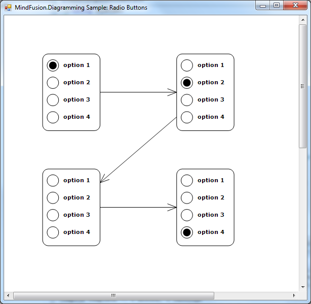
Let’s try it – create a few nodes and run the application, you’ll see the screen shown below:

var node1 = new OptionNode();
node1.Bounds = new RectangleF(20, 20, 30, 40);
node1.SelectedOption = 0;
diagram.Nodes.Add(node1);

var node2 = new OptionNode();
node2.Bounds = new RectangleF(90, 20, 30, 40);
node2.SelectedOption = 1;
diagram.Nodes.Add(node2);

var node3 = new OptionNode();
node3.Bounds = new RectangleF(20, 80, 30, 40);
node3.SelectedOption = null;
diagram.Nodes.Add(node3);

var node4 = new OptionNode();
node4.Bounds = new RectangleF(90, 80, 30, 40);
node4.SelectedOption = 3;
diagram.Nodes.Add(node4);

for (int i = 0; i < diagram.Nodes.Count - 1; i++)
	diagram.Factory.CreateDiagramLink(
		diagram.Nodes[i], diagram.Nodes[i + 1]);

Radio buttons in MindFusion diagram nodes

To be fair, this kind of nodes is simple enough to implement using standard TableNode class where radio button graphics are either custom drawn or set as Image inside table cells in first column, and text displayed in second column. However the radio buttons can be mixed with other components in CompositeNodes to implement more complex user interfaces than ones possible with tables.

For more information on MindFusion flow diagramming libraries for various desktop, web and mobile platforms, see MindFusion.Diagramming Pack page.

Enjoy!

Display Petri nets using MindFusion diagram component.

In this post we show how to build a Petri net using MindFusion.Diagramming for WinForms. Petri nets are used to model and study distributed systems. A net contains places, transitions and arcs. A place represents possible state of the system, and a transition represents the change from one state to another. Arcs connect places to transitions and show the flow direction.

First, create a new .NET Windows Forms project and add a Model.cs file to it where we’ll define Petri net model classes

public class Net
{
	public List Places { get; set; }
	public List Transitions { get; set; }
	public List Arcs { get; set; }

	public Net()
	{
		Places = new List();
		Transitions = new List();
		Arcs = new List();
	}
}

public class Node
{
	public string Label { get; set; }
}

public class Place : Node
{
	public int Tokens { get; set; }
}

public class Transition : Node
{
}

public class Arc
{
	// Arcs run from a place to a transition or vice versa,
	// never between places or between transitions.

	public Arc(Place input, Transition output)
	{
		Input = input;
		Output = output;
	}

	public Arc(Transition input, Place output)
	{
		Input = input;
		Output = output;
	}

	public Node Input { get; private set; }
	public Node Output { get; private set; }

	public int Multiplicity { get; set; }
}

Now we can create a simple Petri net:

Net CreateSampleNet()
{
	var net = new Net();

	var p1 = new Place { Label = "P1", Tokens = 1 };
	var p2 = new Place { Label = "P2", Tokens = 0 };
	var p3 = new Place { Label = "P3", Tokens = 2 };
	var p4 = new Place { Label = "P4", Tokens = 1 };

	net.Places.AddRange(new[] { p1, p2, p3, p4 });

	var t1 = new Transition { Label = "T1" };
	var t2 = new Transition { Label = "T2" };

	net.Transitions.AddRange(new[] { t1, t2 });

	var a1 = new Arc(p1, t1);
	var a2 = new Arc(t1, p2);
	var a3 = new Arc(t1, p3);
	var a4 = new Arc(p2, t2);
	var a5 = new Arc(p3, t2);
	var a6 = new Arc(t2, p4);
	var a7 = new Arc(t2, p1);

	net.Arcs.AddRange(new[] { a1, a2, a3, a4, a5, a6, a7 });

	return net;
}

Next, drop a DiagramView and Diagram objects on the form which we’ll use to visualize the net. Add the following method to create diagram elements representing the model objects, and run LayeredLayout to arrange them:

void BuildDiagram(Net net)
{
	var nodeMap = new Dictionary<node, diagramnode="">();

	var placeBounds = new RectangleF(0, 0, 16, 16);
	var transBounds = new RectangleF(0, 0, 6, 20);

	foreach (var place in net.Places)
	{
		var node = diagram.Factory.CreateShapeNode(placeBounds);
		node.Text = place.Label;
		node.TextFormat.LineAlignment = StringAlignment.Far;
		node.Shape = Shapes.Ellipse;
		node.Tag = place.Tokens;
		node.CustomDraw = CustomDraw.Additional;
		nodeMap[place] = node;
	}

	foreach (var trans in net.Transitions)
	{
		var node = diagram.Factory.CreateShapeNode(transBounds);
		node.Text = trans.Label;
		node.TextFormat.LineAlignment = StringAlignment.Far;
		node.Shape = Shapes.Rectangle;
		nodeMap[trans] = node;
	}

	foreach (var arc in net.Arcs)
	{
		var link = diagram.Factory.CreateDiagramLink(
			nodeMap[arc.Input], nodeMap[arc.Output]);
		link.Tag = arc.Multiplicity;
		link.HeadShape = ArrowHeads.PointerArrow;
	}

	var layout = new LayeredLayout();
	layout.Orientation = Orientation.Horizontal;
	layout.StraightenLongLinks = true;
	layout.Arrange(diagram);
}</node,>

We will use the DrawNode custom draw event to render marks associated with each place. Another possibility is to create a custom node class and override its Draw method.

void OnDrawNode(object sender, DrawNodeEventArgs e)
{
	var node = e.Node;
	var g = e.Graphics;

	if (node.Tag is int)
	{
		var tokens = (int)node.Tag;
		var cx = node.Bounds.Width / 2;
		var cy = node.Bounds.Height / 2;

		if (tokens == 1)
		{
			float r = cx / 2;
			DrawMark(cx, cy, r, g);
		}
		else if (tokens == 2)
		{
			float r = 2 * cx / 5;
			DrawMark(cx / 2, cy, r, g);
			DrawMark(3 * cx / 2, cy, r, g);
		}
		else if (tokens == 3)
		{
			float r = cx / 3;
			float y2 = 4 * cy / 3;
			DrawMark(cx, 2 * cy / 5, r, g);
			DrawMark(cx / 2, y2, r, g);
			DrawMark(3 * cx / 2, y2, r, g);
		}
	}
}

void DrawMark(float x, float y, float r, IGraphics g)
{
	g.FillEllipse(Brushes.Black, x - r, y - r, r * 2, r * 2);
}

Finally, set some appearance properties and call the methods above to build the diagram:

public MainForm()
{
	InitializeComponent();

	diagram.ShadowsStyle = ShadowsStyle.None;
	diagram.DiagramLinkStyle.Brush = new MindFusion.Drawing.SolidBrush(Color.Black);
	diagram.ShapeNodeStyle.Brush = new MindFusion.Drawing.SolidBrush(Color.White);
	diagram.ShapeNodeStyle.FontSize = 10f;
	diagram.ShapeNodeStyle.FontStyle = FontStyle.Bold;

	var textAbove = new[]
	{
		new LineTemplate(-100, -100, 200, -100),
		new LineTemplate(200, -100, 200, 0),
		new LineTemplate(200, 0, -100, 0),
		new LineTemplate(-100, 0, -100, -100)
	};
	Shapes.Ellipse.TextArea = textAbove;
	Shapes.Rectangle.TextArea = textAbove;

	var net = CreateSampleNet();
	BuildDiagram(net);
}

The final result is displayed below.
Petri net diagram

The complete sample project is available for download here:
PetriNet.zip

For more information on Petri nets, see this Wikipedia article:
http://en.wikipedia.org/wiki/Petri_net

All MindFusion.Diagramming libraries expose the same programming interface, so most of the sample code shown above will work with only a few modifications in WPF, ASP.NET, Silverlight and Java versions of the control.

Enjoy!

Nested DataRanges in MindFusion Report Application

In this tutorial we are going to build a report with nested data ranges. In our case, we are going to retrieve all categories from the sample Norhtwind database. For each category we will get all products in it, which is the nested data range.

I. Preparing the Project

We create a new WinForms project and add a new DataSet from the Nortwind database. We choose all fields from the Categories and Products tables. Then we add a new item from the menu “Project -> Add -> New Item -> MindFusion Report” from the dialog that appears.

Adding the MindFusion Report item.

Adding the MindFusion Report item.

Drag and drop the nwindDataSet, CategoriesTableAdapter and ProductsTableAdapter on the report form. Finally, in the code behind fill the two adapters:

 productsTableAdapter1.Fill(nwindDataSet1.Products);
 categoriesTableAdapter1.Fill(nwindDataSet1.Categories); 

II. The Categories DataRange

We create the first data range by right clicking on the newly created report. There we see “Create Data Range from Data Source”. We choose the categories table and two fields – CategoryName and Picture. When the data range is generated we resize the picture to make it bigger.

Create DataRange context menu.

Create DataRange context menu.

III. Running the Report

We would use MindFusion ReportViewer to preview what we’ve done so far. We drag it from the Toolbox and place it on the form, which shows when the application runs. We compile the project and see that the Report1 class that we’ve created appears in the Toolbox, under the Data tab. This means we can create instances of our report just by drag and drop. We drag the Report1 icon and drop it on Form1. We have a report11 instance, which we assign to the Report property of the ReportView in the property grid.

Dragging the Report1 item.

Dragging the Report1 item.

Finally, we run the report:

report11.Run();

IV. The Nested DataRange

It’s time to create the second DataRange. We right-click the Report1 form and choose again “Create DataRange from Data Source.” This time we choose the Products table and we choose ProductName, UnitsInStock and UnitPrice fields. This time we check the “Generate Header” checkbox at the bottom. The second DataRange is ready. Nesting it is very easy. We resize the first DataRange to make it wider and just drag and drop the second DataRange in it. What is important is to set the MasterDetailRelation property. It must be the name of the relation between the two tables that provide data for the two DataRange-s. We can see it by clicking on the nwindDataSet -> “Edit DataSet with Designer. There we click on the relation between or two tables and see it is called “CategoriesProducts”. We place this name as a value to the MasterDetailRelation property.

Master detail relationship between the Products and Categories table.

Master detail relationship between the Products and Categories table.

V. Run the report

We run the report and see that everything is in place: the categories are listed with their picture, each category lists all its products.

VI. Style Adjustments

Finally let’s add some appearance optimizations that will make the report look better and thus be easier to read. First, we make the background of the Category label darker.

Then we make the product lines with alternating colors. This is done in the property grid for the dataRange2 object -> AlternatingBackground property.

We add a light gray border to the first data range with the Border property editor and we add a bottom margin of 30 mm. Here is the final look of the report:

Nested DataRange-s: the final report.

Nested DataRange-s: the final report.

You can download the sample from this link:

Download Nested DataRanges MindFusion Reporting Sample

More about MindFusion Reporting for WinForms component can be found here.

Create a musical score writer using MindFusion diagram component.

In this example we’ll show how to use various features of MindFusion.Diagramming API to create a musical score editor:

Custom node types
We’ll create a StaffNode class to represent the staff, and NoteNode class to represent a musical note.

Grouping
NoteNodes will be attached to the StaffNode they were dropped onto (or nearby). If users move the staff around, the notes from the group will follow it.

Custom drawing logic
We’ll show how to draw custom graphics by overriding DrawLocal method of base DiagramNode class.

Using SVG images
We’ll show how to load an SVG image (for the G clef) and draw it as part of staff graphics.

NodeListView control
NodeListView contains prototypical node instances whose clones are added to the diagram using drag-and-drop operations. We’ll add a staff and several notes to the list to let users drag them to the score diagram.

The completed sample project can be downloaded from this link:
ScoreWriter.zip

Let’s start by defining StaffNode class to draw staves in the score diagram, and implement its Draw methods to draw five lines:

public class StaffNode : DiagramNode
{
	public StaffNode()
	{
		var rect = Bounds;
		rect.Width = 200;
		SetBounds(rect, false, false);

		// disable vertical resize
		EnabledHandles =
			AdjustmentHandles.ResizeMiddleLeft |
			AdjustmentHandles.Move |
			AdjustmentHandles.ResizeMiddleRight;
	}

	public StaffNode(StaffNode prototype) : base(prototype)
	{
	}

	public override void DrawLocal(IGraphics graphics, RenderOptions options)
	{
		base.DrawLocal(graphics, options);

		for (int i = 0; i < 5; i++)
		{
			float y = i * Bounds.Height / 4;
			using (var pen = EffectivePen.CreateGdiPen())
				graphics.DrawLine(pen, 0, y, Bounds.Width, y);
		}
	}

	public override void DrawShadowLocal(IGraphics graphics, RenderOptions options)
	{
	}
}

Next, load an SVG drawing representing G clef and draw it at appropriate position. We’ll also override GetRepaintRect method to accommodate for parts of the clef that are drawn outside the staff’s boundaries:

static SvgContent gClef;

static StaffNode()
{
	gClef = new SvgContent();
	gClef.Parse("GClef.svg");
}

public override void DrawLocal(IGraphics graphics, RenderOptions options)
{
	// ...

	var rect = GetLocalBounds();
	rect.Inflate(0, 8);
	rect.X = 2;
	rect.Width = 14;
	gClef.Draw(graphics, rect);
}

public override RectangleF GetRepaintRect(bool includeConnected)
{
	var rect = base.GetRepaintRect(includeConnected);
	rect.Inflate(0, 8);
	return rect;
}

Create an initial StaffNode instance from Form.Load event:

var initialStaff = new StaffNode();
initialStaff.Move(10, 10);
diagram.Nodes.Add(initialStaff);

If you run the project now, you should see the following diagram:
score writer diagram in c#

Next, define the Duration enumeration and NoteNode class to represent musical notes of various durations:

enum Duration
{
	Whole,
	Half,
	Quarter,
	Eighth,
	Sixteenth
}

class NoteNode : DiagramNode
{
	public NoteNode()
	{
		Bounds = new RectangleF(0, 0, 6, 6);
		Duration = Duration.Whole;
	}

	public NoteNode(Duration duration)
	{
		Bounds = new RectangleF(0, 0, 6, 6);
		Duration = duration;
	}

	public Duration Duration { get; set; }

	int position = 0;
}

Implement NoteNode.Draw methods as follows:

public override void DrawLocal(IGraphics graphics, RenderOptions options)
{
	base.DrawLocal(graphics, options);

	var cx = Bounds.Width / 2;
	var cy = Bounds.Height / 2;

	var gs = graphics.Save();
	graphics.TranslateTransform(cx, cy);
	graphics.RotateTransform(-10);
	graphics.TranslateTransform(-cx, -cy);

	var bounds = GetLocalBounds();
	bounds.Inflate(0, -bounds.Width / 10);
	var path = new GraphicsPath();
	path.AddEllipse(bounds);

	if (Duration == Duration.Whole || Duration == Duration.Half)
	{
		bounds.Inflate(-bounds.Width / 8, -bounds.Width / 6);
		path.AddEllipse(bounds);
	}
	graphics.FillPath(Brushes.Black, path);

	graphics.Restore(gs);

	if (position < -1 || position > 8)
	{
		// draw ledger lines if above or below staff
		var pen = EffectivePen.CreateGdiPen();
		var staff = (StaffNode)MasterGroup.MainItem;
		var yoff = staff.Bounds.Y - Bounds.Y;
		int i1 = position < -1 ? position : 9;
		int i2 = position < -1 ? -2 : position;
		for (int i = i1; i <= i2; i++)
		{
			if (i % 2 != 0)
				continue;
			var y = yoff + i * staff.Bounds.Height / 8;
			graphics.DrawLine(pen, -2, y, Bounds.Width + 2, y);
		}
		pen.Dispose();
	}

	if (Duration != Duration.Whole)
	{
		// draw stem
		float x = Bounds.Width;
		float y = Bounds.Height / 2;
		var pen = new System.Drawing.Pen(Color.Black, 0.5f);
		graphics.DrawLine(pen,
				            x - pen.Width / 2, y,
				            x - pen.Width / 2, y - Bounds.Height * 2);
		pen.Dispose();
	}

	if (Duration == Duration.Eighth || Duration == Duration.Sixteenth)
	{
		DrawFlag(graphics,
				    bounds.Width,
				    bounds.Height / 2 - bounds.Height * 2,
				    bounds.Width + 1,
				    bounds.Height);
	}

	if (Duration == Duration.Sixteenth)
	{
		DrawFlag(graphics,
				    bounds.Width,
				    bounds.Height - bounds.Height * 2,
				    bounds.Width + 1,
				    bounds.Height);
	}
}

void DrawFlag(IGraphics graphics, float x, float y, float w, float h)
{
	float sh = h / 2;
	float sw = w / 3;

	var pen = new System.Drawing.Pen(Color.Black, 0.5f);
	x -= pen.Width / 2;
	graphics.DrawBezier(pen,
			            x, y,
			            x, y + sh,
			            x + sw * 1.2f, y + 2 * sh,
			            x + sw, y + 3 * sh);
	pen.Dispose();
}

public override void DrawShadowLocal(IGraphics graphics, RenderOptions options)
{
}

public override RectangleF GetRepaintRect(bool includeConnected)
{
	var r = Bounds;
	r.Y -= r.Height * 2;
	r.Height *= 3;
	r.Width *= 2;
	return r;
}

Now, drag a NodeListView to the form and populate it from Load handler:

nodeListView.AddNode(new StaffNode());

nodeListView.DefaultNodeSize = new SizeF(6, 6);
nodeListView.AddNode(new NoteNode(Duration.Whole));
nodeListView.AddNode(new NoteNode(Duration.Half));
nodeListView.AddNode(new NoteNode(Duration.Quarter));
nodeListView.AddNode(new NoteNode(Duration.Eighth));
nodeListView.AddNode(new NoteNode(Duration.Sixteenth));

Drag and drop will not work just yet. First, we must enable the DiagramView.AllowDrop property to accept drag-and-drop events. Next, the custom classes must implement a copy constructor and serialization methods to be able to instantiate them through OLE drag events:

public NoteNode(NoteNode prototype) : base(prototype)
{
	Duration = prototype.Duration;
}

protected override void SaveTo(System.IO.BinaryWriter writer, PersistContext context)
{
	base.SaveTo(writer, context);
	context.Writer.Write((int)Duration);
}

protected override void LoadFrom(System.IO.BinaryReader reader, PersistContext context)
{
	base.LoadFrom(reader, context);
	Duration = (Duration)context.Reader.ReadInt32();
}

As a final touch for this example, let’s implement aligning notes to staves’ lines and spaces. First lets declare a helper method that returns the nearest StaffNode at specified location in diagram:

static class DiagramExtensions
{
	static public StaffNode NearestStaff(this Diagram diagram, PointF point)
	{
		var staves = diagram.Nodes.OfType();

		StaffNode nearest = null;
		float minDist = float.MaxValue;

		foreach (var staff in staves)
		{
			if (staff.ContainsPoint(point))
				return staff;

			var borderPoint = staff.GetNearestBorderPoint(point);
			var dist = Utilities.Distance(borderPoint, point);
			if (dist < minDist)
			{
				minDist = dist;
				nearest = staff;
			}
		}

		return minDist < 20 ? nearest : null;
	}
}

Next, implement StaffNode.Align method that aligns its argument to a line or space in the staff:

public PointF Align(PointF point, out int position)
{
	// align to pitch line/space

	float h = Bounds.Height / 8;
	float offset = point.Y - Bounds.Y;
	position = (int)Math.Round(offset / h);
	offset = (float)Math.Round(offset / h) * h;
	point.Y = Bounds.Y + offset;
	return point;
}

Add NoteNode.AlignToStaff method that will find nearest StaffNode and align the note’s position to the staff.

public StaffNode AlignToStaff()
{
	position = 0;

	var staff = Parent.NearestStaff(GetCenter());
	if (staff == null)
		return null;

	var alignedPoint = staff.Align(GetCenter(), out position);
	alignedPoint.X -= Bounds.Width / 2;
	alignedPoint.Y -= Bounds.Height / 2;
	Move(alignedPoint.X, alignedPoint.Y);

	return staff;
}

We can align notes after drag-and-drop from NodeListView by handling diagram’s NodeCreated event. We’ll use the same handler to attach notes to that staff, so that if users move a StaffNode, its attached NoteNodes will follow.

private void OnNodeCreated(object sender, NodeEventArgs e)
{
	var note = e.Node as NoteNode;
	if (note != null)
	{
		var staff = note.AlignToStaff();
		if (staff != null)
			note.AttachTo(staff, AttachToNode.TopLeft);

		note.HandlesStyle = HandlesStyle.MoveOnly;
	}
}

Finally, override NoteNode.CompleteModify to align notes after user moves them to a different position on the staff or to another staff in the score:

protected override void CompleteModify(PointF end, InteractionState ist)
{
	base.CompleteModify(end, ist);

	var staff = AlignToStaff();
	if (staff != null)
		AttachTo(staff, AttachToNode.TopLeft);
	else
	{
		Detach();
	}
}

Let’s run the project and compose some music 🙂
.net diagram control

A fully-featured scorewriter software would also allow for drawing rest, sharp and flat symbols, C and F clefs, and some other musical notation features, but these are left as exercise to the reader 😉

The code above uses MindFusion’s .NET API and can be used with Windows Forms, WPF, Silverlight and ASP.NET diagramming components. The Java API for Android and desktop Swing application will look similar, with setter method calls instead of property assignments.

You can download the trial version of any MindFusion.Diagramming component from this page.

Enjoy!

Layout Management with the WinForms Dock Control

In this post we will show you how to build a sample application with customizable layout based on the WinForms Dock control, which is part of MindFusion WinForms pack. You can find further details about the control at its web page.

For the purpose of the demonstration we’ve chosen an entertaining topic – a cooking recipes electronic book. Our book so far has only three recipes, all for sweets. Lets start by looking at the

I. Architecture of the sample.

The sample has two custom classes – Ingredient and Recipe. Each Ingredient has quantity, name and an image, which illustrates it. The Recipe class holds a strongly typed list with Ingredient objects, the title for each recipe, an image for the recipe, an icon for the recipe and preparation instructions.

The application consists of the dock control, which contains four DockItem-s : for the recipes, for their images, for their ingredients and with the preparation instructions. Any dock item can be dragged, dropped, aligned, minimized, hidden etc.

The API of the cook book application

The API of the cook book application

II. The Dock Control.

We create an empty WinForms project and add the Dock control from the toolbox. The dock control fills the entire client area:

this.dockControl1.Dock = System.Windows.Forms.DockStyle.Fill;         
this.dockControl1.Location = new System.Drawing.Point(0, 0);           
this.dockControl1.Size = new System.Drawing.Size(784, 562);

These properties are set in the Property grid.

Each dock item is created with a title and id, which helps us identify it.

titleItem = new DockItem() { Header = "Recipe Name", Id = "Name" };
titleItem.DockStyle = DockStyle.Left;      
titleItem.Content = GetContent("Name");

The DockStyle property is responsible for the initial layout of the dock item. You can choose among various dock styles – fill, bottom, top and more.

The GetContent method is very important. It prepares the controls that will be placed into each dock item and returns the appropriate one according to the parameter.

Once the dock item is created, let’s not forget to add it:

dockControl1.Items.Add(titleItem);

III. Creating the Content.

Let’s see how the content for a dock item is created. Let’s take the grid with the ingredients. It is identified with the “Ingredients” id:

private Control GetContent(string contentType)
{
  Control control = null;
  ....
  else if (contentType == "Ingredients")
         {                
             grid = new DataGridView();
             grid.DefaultCellStyle.BackColor = Color.FromArgb(247, 226, 189);
             grid.Dock = DockStyle.Fill;
             grid.MultiSelect = false;
             grid.DataSource = selectedRecipe.Ingredients;
             grid.RowTemplate.MinimumHeight = 35;
            
             grid.RowHeadersWidthSizeMode =
            DataGridViewRowHeadersWidthSizeMode.DisableResizing;
             grid.ColumnHeadersHeightSizeMode = DataGridViewColumnHeadersHeightSizeMode.DisableResizing;
             grid.AutoSizeColumnsMode = DataGridViewAutoSizeColumnsMode.Fill;
             grid.SelectionMode = DataGridViewSelectionMode.FullRowSelect;
             grid.BackgroundColor = Color.FromArgb(253, 244, 247);

             control = grid; 
         }
...
return control;

The idea is clear: you create the control, which will be rendered in the dock item and assign it to DockItem.Content. Here we make different customization for the grid – we change the color of table rows, adjust the height, turn off multiple row select and more.

IV. Changing the Content.

We change the content by handling the SelectedIndexChanged event for the ListView, which lists our recipes. When the user selects a new list item, we extract its Recipe and change the content of the other DockItem-s:

selectedRecipe = recipes[recipesListView.SelectedIndices[0]];
tb.Text = selectedRecipe.Preparation;
grid.DataSource = selectedRecipe.Ingredients;
pictureBox.Image = Image.FromFile(selectedRecipe.ImageUrl);

Here is the final output of the sample application:

MindFusion WinForms Dock COntrol

A Sample electronic cook book based on MindFusion WinForms Dock Control

You can download the sample directly from this link:

MindFusion WinForms Layout Control Sample: Electronic Cook Book in C#

MindFusion WinForms Layout Control Sample: Electronic Cook Book in VB.NET

Enjoy the fast, easy and straight-forwarded manner in which you can create a WinForms application with a flexible layout and multiple panels.