Different-size Icons in the Js Diagram NodeListView

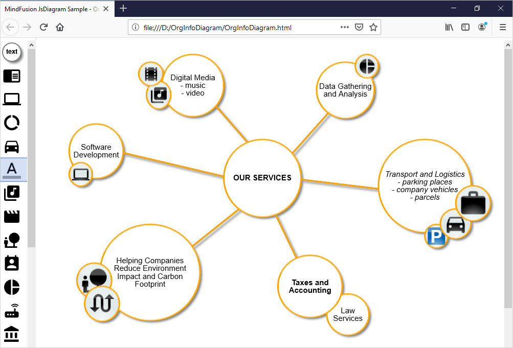
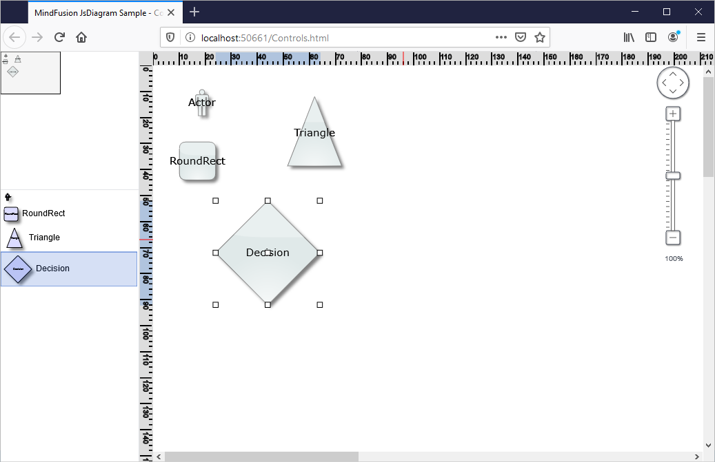
In this blog post we will learn how to add a NodeListView control to a Diagram and how to set its ShapeNode -s to a different size. When ShapeNode -s are dragged from the NodeListView the instances that will be created are proprtional in size to the size of the ShapeNode that was dragged. Here is a screenshot of the final application:

I. General Settings

We create an HTML page and add to it references to the MindFusion JavaScript files that represent the diagramming library:

<script src="MindFusion.Common.js" type="text/javascript"></script>
<script src="MindFusion.Diagramming.js" type="text/javascript"></script>
<script src="Controls.js" type="text/javascript"></script>

The last reference is to the Controls JavaScript file, where the code for the application is located.

Then we create two Canvas-es: one is for the NodeListView and the other is for the Diagram The NodeListView component is bound to the canvas element below:

<div style="width: 200px; height: 100%; overflow-y: auto; overflow-x: hidden; position: absolute; top: 201px; left: 0px; right: 0px; bottom: 0px;">
    <canvas id="nodeList" width="200"></canvas>
</div>
......
<!-- The Diagram component is bound to the canvas element below -->
<div style="position: absolute; left: 0px; top: 0px; right: 0px; bottom: 0px; overflow: auto;"> <canvas id="diagram" width="2100" height="2100">
This page requires a browser that supports HTML 5 Canvas element.
</canvas>
</div>

Both the Diagram and NodeListView controls require Canvas elements to render themselves onto.

II. Initializing the Controls

We create the Diagram using the id that we’ve provided to its Canvas in the web page:

// create a Diagram component that wraps the "diagram" canvas
diagram = Diagram.create(document.getElementById("diagram"));
diagram.setBounds(new MindFusion.Drawing.Rect(0, 0, 500, 500));

We set a bigger size to the diagram in order to make it fill the web page.

We create the NodeListView instance the same way we created the diagram:

// create a NodeListView component that wraps the "nodeList" canvas
var nodeList = MindFusion.Diagramming.NodeListView.create(document.getElementById("nodeList"));
nodeList.setTargetView(document.getElementById("diagram"));

Now we need to add the settings that will make the ShapeNode -s different in size when rendered onto the list:

nodeList.setIconSize(null);

The setIconSize method is used to specify the default size of nodes in the NodeListView When we set the size to null, the control draws each node in the NodeListView with the size that was assigned to it:

function initNodeList(nodeList, diagram)
{
    // add some nodes to the NodeListView
    var shapes = ["Actor", "RoundRect", "Triangle", "Decision"];
    for (var i = 0; i < shapes.length; ++i)
    {
        var node = new MindFusion.Diagramming.ShapeNode(diagram);
        node.setText(shapes[i]);
        node.setShape(shapes[i]);
        node.setBounds(new MindFusion.Drawing.Rect(0, 0, (i+1)*10, (i+1)*10));
        nodeList.addNode(node, shapes[i]);
    }
}

Here we increase the size of wach ShapeNode with 10 points on each itereation. This makes the icons with various size but does not create them with different size when dropped on the diagram. In order to do this we must set:

nodeList.setDefaultNodeSize (null);

setDefaultNodeSize specifies the size of those nodes that are created when a ShapeNode is dropped on the Diagram area. By setting this size to null we tell the control to read the size of the new ShapeNode from the instance in the NodeListView control.

With that our sample is ready. You can download the source code from this link:

JavaScript NodeListView with Various Size Nodes: Download Sample

About Diagramming for JavaScript: This native JavaScript library provides developers with the ability to create and customize any type of diagram, decision tree, flowchart, class hierarchy, graph, genealogy tree and more. The control offers rich event set, numerous customization options, animations, graph operations, styling and themes. You have more than 100 predefined nodes, table nodes and more than 15 automatic layout algorithms. Learn more about Diagramming for JavaScript at https://mindfusion.eu/javascript-diagram.html.

JavaScript Diagram with Chart Nodes

In this blog post we will create DiagramNode instances that render a chart. The charts get resized according to the size of the node. We will use two MindFusion libraries for JavaScript – Charting and Diagramming. You can run the sample online from this link:

I. Project Setup

We will use a web page that will hold the HTML Canvas element that we need in order to render the diagram:

<div style="width: 100%; height: 100%; overflow: scroll;">
    <canvas id="diagram" width="2100" height="2100" style="background:#f0f0f0;">
        This page requires a browser that supports HTML 5 Canvas element.
    </canvas>
</div>

We give the diagram’s Canavs big width and height and we also provide an id. The id is important because we will need to access the Canvas from code.

We add the scripts that we need in order to use the Charting and Diagramming libraries:

<script src="Scripts/MindFusion.Common.js" type="text/javascript"></script>
<script src="Scripts/MindFusion.Diagramming.js" type="text/javascript"></script>
<script src="Scripts/MindFusion.Charting.js" type="text/javascript"></script>

We add the references at the end of the web page, just before the closing BODY tag. We also need to add a reference to a JavaScript file that will hold the code for our sample. We name it “PieNode.js”.

II. The Diagram

In the code-behind file we create a diagram instance. We use the DOMContentLoaded event to initialize our diagram:

document.addEventListener("DOMContentLoaded", function ()
{
// create a Diagram component that wraps the "diagram" canvas
diagram = MindFusion.Diagramming.Diagram.create(document.getElementById("diagram"));
diagram.setBehavior(MindFusion.Diagramming.Behavior.LinkShapes);
diagram.setLinkHeadShapeSize(2);
diagram.setBounds(new Rect(0, 0, 2000, 2000));

// draw a pie when the user creates a node
diagram.addEventListener(Events.nodeCreated, onNodeCreated);

});

The Behavior enumeration lists various modes of behavior for the diagram. We choose Behavior.LinkShapes, which creates nodes, when the mouse is dragged
over an empty area and connects the nodes if the mouse is dragged from an existing node. We set tbe bounds of the diagram to a big Rect which guarantees that the user can draw nodes anywhere on the visible area. When the user draws towards the edge of the browser, the diagram control expands automatically.

Finally, we add an event handler for the nodeCreated event.

//nodeCreated event handler
function onNodeCreated(sender, args)
{
	var node = args.getNode();
	
	var nBounds = node.getBounds ();
	var topLeftCoord = diagram.docToClient(nBounds.topLeft());
	var bottomRightCoord = diagram.docToClient(nBounds.bottomRight());
	.......................................................
}

At first we get the node that was created. Then we need to get its actual size, for which we use the docToClient method that converts between diagram and browser measure units. We get the two coordinates of the node’s bounding rectangle.

We create then a Canvas, which takes the size of the node’s rectangle:

............................................
.....................................................
var pieChartCanvas = document.createElement('canvas');
pieChartCanvas.width = bottomRightCoord.x - topLeftCoord.x;
pieChartCanvas.height = bottomRightCoord.y - topLeftCoord.y;

We then add this temp canvas to the body of the web page and call a method “createPie” where we draw the pie chart. Once the chart is drawn we get the URL of the image and set is to the node with the setImageLocation method. We remove the Canvas from the tree with the elements because we want to use for the next node.

//create a temporary Canvas for the pie chart
//to draw itself upon
document.body.appendChild(pieChartCanvas);
createPie(pieChartCanvas);
var pieImageLocation = pieChartCanvas.toDataURL();
node.setImageLocation(pieImageLocation);
document.body.removeChild(pieChartCanvas);

III. The Chart

We create a pie chart in the Canvas provided to the createPie method:

//draw a pie chart on the provided canvas
function createPie(pieChartCanvas)
{
	var pieChart = new Controls.PieChart(pieChartCanvas);
	pieChart.startAngle = 45;			
	pieChart.showLegend = false;
	pieChart.title = "Sales";
	pieChart.titleMargin = new Charting.Margins(0, 10, 0, 0);
	pieChart.chartPadding = 3;
...........................

We set some appearance properties to make the chart look the way we want – change the start angle of the pie, add a title and title margin, hide the legend. Then we create a PieSeries which holds the data and the labels of the pie. We assign the PieSeries to the series property of the pie chart:

// create sample data
var values = new Collections.List([20.00, 30.00, 15.00, 40.00]);
pieChart.series = new Charting.PieSeries(
	values,
	new Collections.List(["20", "30", "15", "40"]),
null);

We style the chart with an instance of the PerElementSeriesStyle class, which colors all elements of a Series with the consequtive Brush and stroke from its brushes and strokes collections. Then we adjust the dataLabelsFontSize to match the size of the canvas. We make the labels be drawn with a white brush using the dataLabelsBrush property. Finally we call draw to render the pie.

var brushes = new Collections.List(
		[
			new Drawing.Brush("#0455BF"),
			new Drawing.Brush("#033E8C"),
			new Drawing.Brush("#F24405"),
			new Drawing.Brush("#F21905")
		]);

	var seriesBrushes = new Collections.List();
	seriesBrushes.add(brushes);

	var strokes = new Collections.List(
		[
			new Drawing.Brush("#c0c0c0")
		]);

	var seriesStrokes = new Collections.List();
	seriesStrokes.add(strokes);

	pieChart.plot.seriesStyle = new Charting.PerElementSeriesStyle(seriesBrushes, seriesStrokes);
	pieChart.theme.highlightStroke = new Drawing.Brush("#000063");
	pieChart.theme.dataLabelsFontSize = pieChartCanvas.height/20;
	pieChart.theme.dataLabelsBrush = new Drawing.Brush("#FFFFFF");

	pieChart.draw();

And with that the sample is ready. You can download the source code together with all MindFusion JavaScript libraries used from:

https://mindfusion.eu/samples/javascript/diagram/PieNodes.zip

About Diagramming for JavaScript: This native JavaScript library provides developers with the ability to create and customize any type of diagram, decision tree, flowchart, class hierarchy, graph, genealogy tree and more. The control offers rich event set, numerous customization options, animations, graph operations, styling and themes. You have more than 100 predefined nodes, table nodes and more than 15 automatic layout algorithms. Learn more about Diagramming for JavaScript at https://mindfusion.eu/javascript-diagram.html.
About Charting for JavaScript: MindFusion library for interactive charts and gauges. It supports all common chart types including 3D bar charts. Charts can have a grid, a legend, unlimited number of axes and series. Scroll, zoom and pan are supported out of the box. You can easily create your own chart series by implementing the Series interface.
The gauges library is part of Charting for JavaScript. It supports oval and linear gauge with several types of labels and ticks. Various samples show you how the implement the gauges to create and customize all popular gauge types: car dashboard, clock, thermometer, compass etc. Learn more about Charting and Gauges for JavaScript at https://mindfusion.eu/javascript-chart.html.

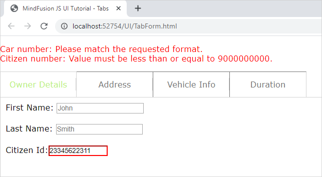
Multi-tabs Form in JavaScript with Validation

In this blog post we will create a form that spans over several tabs. Each tab contains input fields for a specific type of information. There are placeholders and restrictions for each input field. If the provided data is not correct we display a guiding message and select the first tab that has wrong data. All incorrect fields are outlined with red.

I. General Settings

We will use two files for our form – one is a web page and the other a JavaScript file that will hold all JavaScript code for the sample. They both are names TabForm.

In the web page we add references to the css file that holds the theme we’ve chosen:

<link rel="stylesheet" type="text/css" href="themes/light.css">

This is the CSS for the light theme of the MindFusion JavaScript UI controls. There are various themes provided out-of-the-box with the library and you can choose another one.

Then, at the bottom of the web page, before the closing BODY tag we add references to the three JavaScript files that we want to use:

<div style="position: absolute; top: 0px; left: 0; right: 0; bottom: 0;">
    <div id="host">
    </div>
</div>

The first two of them point to the libraries of the UI controls: MindFusion.Common and MindFusion.UI. The other is a reference to the JS code-behind file.

In order to render the TabControl we need a DIV element. So, we create one and give it an id – that is important:

We also add a paragraph with an id and red stroke – it will render text, that describes the error fields and the validation message for each one – if the user has provided wrong data.

II. Creating the Tab Control and the Tab Pages

In the code-behind file we first add mappings to the two namespaces we want to use:

var ui = MindFusion.UI;
var d = MindFusion.Drawing

Then we create an instance of the TabControl in code this way:

// Create a new TabControl.
var host = new ui.TabControl(document.getElementById("host"));
host.width = new ui.Unit(70, ui.UnitType.Percent);
host.height = new ui.Unit(70, ui.UnitType.Percent);
host.theme = "light";

We use the id of the DIV element in the constructor of the TabControl Then we use the theme property to refer to the theme that we want to use. The value of the theme property should be the same as the name of the CSS ile that we referenced in the web page. It can point to a custom theme that you have created as long as the names of the file and the property value match.

We create the first TabPage as an instance of the TabPage class:

// Create four templated tab pages and add them to the host's tabs collection.
var tab1 = new ui.TabPage("Owner Details");
// The HTML of the specified page will be set as the innerHTML of a scrollable div inside the tab content element.
tab1.templateUrl = "page1.html";
host.tabs.add(tab1);

We provide the string that will render in the title of the TabPage in the constructor. Then we set the content that the TabPage will have as a url to the web page that contains it e.g. the TabPage loads a content from a page specified with templateUrl Here is the code for the first page:


In terms of HTML, we have provided each input element with an id, a placeholder value and the necessary restrictions that will validate its content. We strictly use and follow the Validation API of JavaScript, which you can check here: https://www.w3schools.com/js/js_validation_api.asp and here https://developer.mozilla.org/en-US/docs/Web/Guide/HTML/HTML5/Constraint_validation.

III. Data Submission and Validation

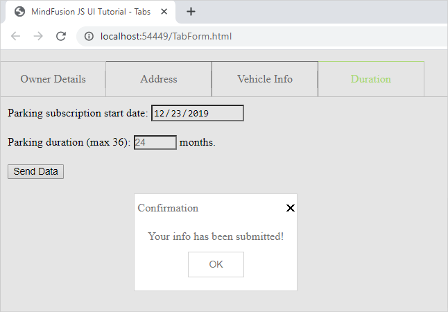
On the last tab of the form, we have placed a submit button:

We wire the event handler of the click action for this button in the contentLoad event of the fourth tab, where the button is:

tab4.contentLoad.addEventListener(tabLoad);
..........................
..........................
function tabLoad(sender, args) {

    let current_datetime = new Date();
    let formatted_date = current_datetime.getFullYear() + "-" + (current_datetime.getMonth() + 1) + "-" + current_datetime.getDate();
    sender.element.querySelector("#start").value = formatted_date;
    sender.element.querySelector("#submit").addEventListener("click", function () {
    submitData(sender);
    });
}

In the event handler we get the current date and format it the way the default DateTime picker HTML control expects to get it. We get each input control through its id and the querySelector of the HTML Document object. The sender in this case is the fourth tab or tab4.

The method that validates the content is submitData:

function submitData(sender) {
    var txt = "";

    var inputObj = tab4.element.querySelector("#start");

    if (!inputObj.checkValidity()) {
        txt += inputObj.name + ": ";
        txt += inputObj.validationMessage + "
";
        inputObj.style["border-color"] = "red";
        host.selectedItem = tab4;
        dataIsCorrect = false;
    } else
        inputObj.style["border-color"] = "gray";
        ....................................

We use querySelector once again to get the input fields on each page one by one. For each one we see if the validity check has failed. If yes, we outline this field in red and append the validation message to a text variable.

We walk through all tabs and all input fields in this same manner and in reverse order. Our aim is that the first tab with error gets selected, even if there are errors in fields further in the form.

Note that if the field is OK we set its border to the default color. This way we reset the appearance of fields that were previously wrong but the user has corrected.

Finally, we assign the text to the content of the paragraph that renders text in red:

...............................
document.getElementById("error").innerHTML = txt;  

    if (txt.length === 0)
        confirmData();

If no errors have been detected – that means the error text is an empty string – we submit the data. The data submission is handled by the confirmData method:

function confirmData() {

    //first tab
    tab1.element.querySelector("#fname").value = "";
    tab1.element.querySelector("#lname").value = "";
    tab1.element.querySelector("#citizen_id").value = "";
    ........................................
    ........................................
     //fourth tab
    tab4.element.querySelector("#duration").value = "";
    let current_datetime = new Date();
    let formatted_date = current_datetime.getFullYear() + "-" + (current_datetime.getMonth() + 1) + "-" + current_datetime.getDate();
    tab4.element.querySelector("#start").value = formatted_date;

    ui.Dialogs.showInfoDialog("Confirmation", "Your info has been submitted!", null, host.element, host.theme);

}

We reset the values of all input fields and we show an instance of MindFusion InfoDialog to inform the user that their data has been successfully collected.

You can download the source code of the sample and all MindFusion themes and libraries used from this link:

https://mindfusion.eu/samples/javascript/ui/TabForm.zip

You can ask technical question about MindFusion JavaScript developer tools at the online forum at https://mindfusion.eu/Forum/YaBB.pl.

About MindFusion JavaScript UI Tools: MindFusion UI libraries are a set of smart, easy to use and customize JavaScript UI components. Each control boasts an intuitive API, detailed documentation and various samples that demonstrate its use. The rich feature set, multiple appearance options and numerous events make the UI controls powerful tools that greatly facilitate the programmers when building interactive JavaScript applications. MindFusion UI for JavaScript is part of MindFusion JavaScript Pack. You can read details at https://mindfusion.eu/javascript-pack.html.

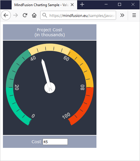
Cost Meter Gauge in JavaScript

In this post we will look at the steps we need to make if we want to create this beautiful gauge below:

The gauge is done with MindFusion Charts and Gauges for JavaScript library. You can download the sample together with all needed libraries from this link.

I. Project Setup

We will build the gauge using the OvalGauge library from MindFusion JS Charts and Gauges control. We add two references, needed for the control to work properly:

<script type="text/javascript" src="Scripts/MindFusion.Common.js"></script>
<script type="text/javascript" src="Scripts/MindFusion.Gauges.js"></script>

We have placed those files in a Scripts folder. We will write the JavaScript code for the gauge in a separate file, which we call ValueGauge.js. This file is at the same directory where the web page is. We add a reference to it as well:

<script type="text/javascript" src="ValueGauge.js"></script>

The web page with our sample contains a table. We use the table to place the control together with a text box. The text box is not needed, but we will use it to give the user the option to set the value of the gauge by typing it not only by dragging the pointer.

<table cellpadding="10">
    <tbody>
        <tr>
            <td>Project Cost (in thousands)</td>
        </tr>
        <tr>
            <td><canvas id="value_meter" width="300" height="300"></canvas></td>
        </tr>
        <tr>
            <td>Cost <input id="cost" style="width: 80px"></td>
        </tr>
    </tbody>
</table>

The gauge will be rendered through an HTML Canvas element. The location and size of the Canvas determine the location and the size of the gauge. It is important that we add an id the Canvas – this way we can reference it in the JavaScript code page, which will be necessary.

II. The Control

Now we start editing the ValueGauge.js file and there we first add mappings to the namespaces of Mindusion.Gauges.js that we will use:

/// 
var Gauges = MindFusion.Gauges;

var d = MindFusion.Drawing;
var OvalScale = Gauges.OvalScale;
var Length = Gauges.Length;
var LengthType = Gauges.LengthType;
var Thickness = Gauges.Thickness;
var Alignment = Gauges.Alignment;
var LabelRotation = Gauges.LabelRotation;
var TickShape = Gauges.TickShape;
var PointerShape = Gauges.PointerShape;

The first line is a reference to the Intellisense file that allows us to use code completion of the API members, if supported by our JavaScript IDE.

Now we need to get the DOM Element that corresponds to the gauge Canvas and use it to create an instance of the OvalGauge class:

var value_meter = Gauges.OvalGauge.create(document.getElementById('value_meter'), false);

III. Gauge Scales

Gauge scales depend on the type of the gauge. For oval gauges we use OvalScale The OvalScale needs to be associated with a gauge and here is how we create it:

var valueScale = new Gauges.OvalScale(value_meter);
valueScale.setMinValue(0);
valueScale.setMaxValue(100);
valueScale.setStartAngle(120);
valueScale.setEndAngle(420);

The OvalScale class offers the full set of properties needed to customize the scale. We use the setMinValue and setMaxValue methods to specify the value range o the gauge. The setStartAngle and setEndAngle specify the arc of the gauge and we set them to 120 and 420 respectively. You see that the arc is 300 degrees, which is less than a full circle – exactly how we want it to be.

We continue our customization by setting the fill and stroke of the scale. We actually do not want the default scale to be rendered at all, so we use setFill and setStroke to specify transparent colors:

valueScale.setFill('Transparent');
valueScale.setStroke('Transparent');
valueScale.setMargin(new Gauges.Thickness(0.075, 0.075, 0.075, 0.075, true));

Now we can continue with the ticks. Each gauge can have major, middle and minor ticks. Those ticks are not rendered by default.

var majorSettings = valueScale.majorTickSettings;
majorSettings.setTickShape(Gauges.TickShape.Line);
majorSettings.setTickWidth(new Gauges.Length(10, Gauges.LengthType.Relative));
majorSettings.setTickHeight(new Gauges.Length(10, Gauges.LengthType.Relative));
majorSettings.setFontSize(new Length(14, LengthType.Relative));
majorSettings.setNumberPrecision(0);
majorSettings.setFill('rgb(46, 52, 66)');
majorSettings.setStroke('rgb(46, 52, 66)');
majorSettings.setLabelForeground('rgb(175, 175, 175)');
majorSettings.setLabelAlignment(Alignment.InnerCenter);
majorSettings.setLabelRotation(LabelRotation.Auto);
majorSettings.setLabelOffset(new Length(6, LengthType.Relative));
majorSettings.setStep(20);
majorSettings.setTickAlignment (Alignment.OuterOutside);

We start the customization with the majorTickSettings They will render labels and want to have one tick with a tep of 20. So, we use setStep to specify 20 as an interval and use setTickWidth and setTickHeight to set the size of the ticks. Those properties can be set to an absolute or relative value – see the LengthType enumeration. We also need to change the default shape of the pointer – we use TickShape rest of the settings are intuitive – setFill and setStroke specify how the ticks are colored. We also use setLabelAlignment to position the labels outside the ticks. setTickAlignment is also an important property -it allows us to change the alignment of the ticks, so they can be drawn inside the scale.

The TickSettings object is similar to MajorTickSettings

var middleSettings = valueScale.middleTickSettings;
middleSettings.setTickShape(TickShape.Line);
middleSettings.setTickWidth(new Gauges.Length(10, Gauges.LengthType.Relative));
middleSettings.setTickHeight(new Gauges.Length(10, Gauges.LengthType.Relative));
middleSettings.setTickAlignment (Alignment.OuterOutside);
middleSettings.setShowTicks(true);
middleSettings.setShowLabels(false);
middleSettings.setFill('rgb(46, 52, 66)');
middleSettings.setStroke('rgb(46, 52, 66)');
middleSettings.setCount(5);

We should note here that setShowLabels is false because we want the labels to appear only at intervals of 20. We also use setCount to specify how many ticks we want between each two adjacent major ticks. The rest of the settings are the same as for MajorTickSettings.

IV. Custom Painting

The painting of the colored sections at the edge of the gauge is custom code. The gauges library provides various events that allow the developer to replace the default gauge drawing with custom drawing – see the Events section of the OvalGauge class.

In our sample we will handle two events:

value_meter.addEventListener(Gauges.Events.prepaintBackground, onPrepaintBackground.bind(this));
value_meter.addEventListener(Gauges.Events.prepaintForeground, onPrepaintForeground.bind(this));

prepaintBackground is raised before the background is painted. We can cancel the default painting or add some custom drawing to it. The same is true for prepaintForeground

function onPrepaintBackground(sender, args)
{
	args.setCancelDefaultPainting(true);

	var context = args.getContext();
	var element = args.getElement();
	var bounds = new d.Rect(0, 0, element.getRenderSize().width, element.getRenderSize().height);
        ..................................
}

In the prepaintBackground event handler we first get the handler to the CanvasRenderingContext2D instance. Then we get the bounds of the painted element. This is the inside of the gauge. Each o the colored segments is pained as an arc. We do not create a path figure to fill – instead we set a very thick lineWidth of the stroke:

context.lineWidth = 25;
var correction = context.lineWidth / 2;
	
//light green segment
context.beginPath();
context.strokeStyle = 'rgb(0, 205, 154)';
context.arc(bounds.center().x, bounds.center().y, bounds.width / 2-correction, 0.665*Math.PI, 1*Math.PI, false);	
context.stroke();

We go on painting this way all colored sections of the gauge, only changing the start and end angles. When we are ready we paint the inside of the gauge. We do it with a full arc:

context.beginPath();
bounds.x += 25;
bounds.y += 25;
bounds.width -= 50;
bounds.height -= 50;
context.fillStyle = '#2e3442';

context.arc(bounds.center().x, bounds.center().y, bounds.width / 2, 0*Math.PI, 2*Math.PI, false);
context.fill();

The complete drawing is done inside the prepaintBackground event handler. So, in the prepaintForeground handler we only need to cancel the default painting:

function onPrepaintForeground(sender, args)
{
    args.setCancelDefaultPainting(true);

};

V. The Gauge Pointer

We need to add a Pointer to the OvalScale of the gauge instance if we want to show one:

var pointer = new Gauges.Pointer();
pointer.setFill('white');
pointer.setStroke("#333333");

pointer.setPointerWidth(new Gauges.Length(90, Gauges.LengthType.Relative));
pointer.setPointerHeight(new Gauges.Length(20, Gauges.LengthType.Relative));

pointer.setShape(Gauges.PointerShape.Needle2);
pointer.setIsInteractive(true);

valueScale.addPointer(pointer);

The size of the pointer is also set in LengthType units. This allows us to have the same pointer size relative to the size of the gauge even if we change the size of the Canvas. We use the PointerShape enumeration to specify the type of pointer we want and then we make it interactive with setIsInteractive As an addition to the default needle of the pointer we want to render a circle at the base of the pointer. We do it with custom drawing:

value_meter.addEventListener(Gauges.Events.prepaintPointer, onPrepaintPointer.bind(this));

First we need to handle the prepaintPointer event. In the event handling code we do the drawing:

function onPrepaintPointer(sender, args)
{	
	//args.setCancelDefaultPainting(true);

	var context = args.getContext();
	var element = args.getElement();
	var size = element.getRenderSize();
	var psize = new d.Size(0.2 * size.width, size.height);

	context.save();
	context.transform.apply(context, element.transform.matrix());

	context.beginPath();
	context.arc(psize.width / 2, psize.height / 2, psize.height*0.75, 0, 2 * Math.PI, false);
	var fill = element.getFill();
	context.fillStyle = Gauges.Utils.getBrush(context, fill, new d.Rect(0, 0, size.width, size.height), false);
	context.fill();
	context.strokeStyle = '#333333';
	context.stroke();

	context.restore();
};

Note that in this case we do not cancel the default painting – we will add to it, rather than replace it. Then we get the CanvasRenderingContext2D and size of the rendered element. What is new here is the transform of the CanvasRenderingContext2D object to the center of the gauge. Then we get the Brush that is used to paint the rest of the pointer and use it to fill the custom part as well. We can set the brush directly, but we prefer to take it from the base element – the Pointer This way if we change settings of the Pointer the color of the custom drawn circle will change automatically as well.

VI. Data Binding

What we would like to do now is bind a change in the text field to the value of the gauge scale. We add a method that does it:

function valueChanged(id)
{
	if (isNaN(this.value)) return;
	var gauge = Gauges.OvalGauge.find(id);
	var pointer = gauge.scales[0].pointers[0];
	pointer.setValue(+this.value);
};

When we call the valueChanged method with the instance of the OvalGauge as an argument, we can get its pointer and set its value to the value of ‘this’. We call the valueChanged in such way, that the ‘this’ reference will be the text field:

var cost = document.getElementById('cost');
cost.onchange = valueChanged.bind(cost, ['value_meter']);

Now when the value changes, the event handler takes the pointer and set its value to the value the user has types.

That is the end of this tutorial. You can download the source code of the sample, together with all MindFusion libraries used from the following link:

Download Value Gauge in JavaScript Source Code

You can use the discussion forum to post your questions, comments and recommendations about the sample or MindFusion charts and gauges.

About MindFusion JavaScript Gauges: A set of two gauge controls: oval and rectangular, with the option to add unlimited nuber of scales and gauges. All gauge elements support complete customization of their appearance. Custom drawing is also possible, where you can replace the default rendering of the gauge element or add to it. The gauge controls include a variety of samples that offer beautiful implementations of the most popular applications of gauges: thermometer, car dashboard, functions, compass, clock, cost meter and more.
Gauges for JavaScript is part of MindFusion charts and Dashboards for JavaScript. Details at https://mindfusion.eu/javascript-chart.html.

Horizontal Full Bar Chart in JavaScript

We use here MindFusion JavaScript library for Charts and Gauges to build this horizontal stacked bar chart that renders custom tooltips:

Run the sample from this link.

You can download the source code together with the libraries used from the link at the bottom of the post.

I. General Setup

We split our chart in two files – one is the web page that hosts an HTML Canvas element that will render the chart. The other file is a JavaScript code-behind file that contains the code for the chart.

We need to add reference to two JavaScript library files that provide the charting and drawing functionality that we need:

MindFusion.Common.js
MindFusion.Charting.js

We place them in a Scripts folder at the same level as our web page and JavaScript code behind file.

<script type="text/javascript" src="Scripts/MindFusion.Common.js"></script>
<script type="text/javascript" src="Scripts/MindFusion.Charting.js"></script>

We also add a reference to the code-behind file that we call StackedBarChart.js:

<script type="text/javascript" src="StackedBarChart.js"></script>

Now we need to create an HTML Canvas element and we must provide it with an id so we can reference it in our JS code:

<canvas id="barChart" width="600px" height="400px"></canvas>

The size of the Canvas determines the size of the chart.

II. Chart Instance and General Settings

We add some namespace mappings that allow us to reference classes from the Chart library in a more consice manner:

var Charting = MindFusion.Charting;
var Controls = MindFusion.Charting.Controls;
var Collections = MindFusion.Charting.Collections;
var Drawing = MindFusion.Charting.Drawing;
var GridType = MindFusion.Charting.GridType;
var ToolTip = Charting.ToolTip;

Then we create an instance of the BarChart control. We need to get the Dom Element that corresponds to the Canvas that we’ve prepared for the chart:

var chartEl = document.getElementById('barChart');
chartEl.width = chartEl.offsetParent.clientWidth;
chartEl.height = chartEl.offsetParent.clientHeight;
var chart = new Controls.BarChart(chartEl, Charting.BarLayout.Stack);

The BarChart constructor supports a second argument that indicates the type of the bar chart to render.

We set the bar chart to horizontal with the horizontalBars property. We also make the bars thicker than normal – the property for this is barSpacingRatio It measures the thickness of the bars as a percente of the bar width.

chart.horizontalBars = true;
chart.barSpacingRatio = 0.2;

III. The Data Series

We want our chart to render labels as tooltips, inside the bars and also we want custom labels at the Y-axis. The predefined BarSeries class accepts 4 lists with data: one for bar data and three with labels inside the bars, at the top of the bars and at the X-axis. So, it is not an exact match for what we want to do and we need to customize it.

We will create our own custom BarSeries that we will call SeriesWithLabels. We will inherit the BarSeries class and override its constructor and getLabel members to provide the desired data for the desired type of labels.

We override the constructor by creating three new variables, which receive the data for the bars and the labels:

var SeriesWithLabels = function (barValues, innerLabels, yLabels) {
    Charting.BarSeries.apply(this, [barValues, innerLabels, yLabels]);
	
	this.yLabels = yLabels;
	this.innerLabels = innerLabels;
	this.values = barValues;
    
};

SeriesWithLabels.prototype = Object.create(Charting.BarSeries.prototype);

Note that before we do anything else in the new constructor we need to call the apply method of the BarSeries class to transfer the provided data to the base class. We also need to create a prototype of the new series and also define its constructor:

 Object.defineProperty(SeriesWithLabels.prototype, 'constructor', {
   	value: SeriesWithLabels,
   	enumerable: false,
   	writable: true
   });

Next we will override the getLabel method. This is the method that returns the correct label according to the requested label kind and the index of the label. We said we want to support inner labels, tooltips and Y-axis labels. So, we make sure our implementation of getLabel returns exactly those labels:

SeriesWithLabels.prototype.getLabel = function (index, kind) {
    if ((kind & Charting.LabelKinds.YAxisLabel) != 0 && this.yLabels)
        return this.yLabels.items()[index];

    if ((kind & Charting.LabelKinds.InnerLabel) != 0 && this.innerLabels)
        return this.innerLabels.items()[index];
	
	if ((kind & Charting.LabelKinds.ToolTip) != 0)
        return getPercentLabel(index, this);
   
    return "";
};

Getting the correct inner and top label is easy – we just return the label at the requested position. What is more work is building the tooltip. We want our tooltip to calculate the portion of the part in the stacked bar the mouse currently is over, to the entire bar. This means we need to calculate the data of all bar portions, which is a combination of the values at the requested position in all three bar series. We do this calculation in a separate method called getPercentLabel.

Before we get to the getPercentLabel method let’s create 3 instances of our custom SeriesWithLabels class:

var labels = new Collections.List([
	"POSITION", "SALARY", "LOCATION", "COLLEAGUES", "WORKTIME"
]);

// create sample data series
var series1 = new SeriesWithLabels(new Collections.List([123, 212, 220, 115, 0.01]), new Collections.List([123, 212, 220, 115, 0]), labels);
var series2 = new SeriesWithLabels(new Collections.List([53, 132, 42, 105, 80]), new Collections.List([53, 132, 42, 105, 80]), null);
var series3 = new SeriesWithLabels(new Collections.List([224, 56, 138, 180, 320]), new Collections.List([224, 56, 138, 180, 320]), null);

The third argument in the SeriesWithLabels constructor is the lists with labels at the Y-axis. We need just one list with labels and we set it with the first series. The other series take null as their third argument.

We need to create a collection with the series and assign it to the series property of the chart:

var series = new Collections.ObservableCollection(new Array(series1, series2, series3));
chart.series = series;

There is a special property called supportedLabels that is member of Series and tells the chart, what type of labels this Series needs to draw. In our case we need to indicate that the first series renders labels at the Y-axis, the inner labels and tooltips. The other two series render inner labels and tooltips:

series1.supportedLabels = Charting.LabelKinds.YAxisLabel | Charting.LabelKinds.InnerLabel | Charting.LabelKinds.ToolTip;
series2.supportedLabels = Charting.LabelKinds.InnerLabel | Charting.LabelKinds.ToolTip;
series3.supportedLabels = Charting.LabelKinds.InnerLabel | Charting.LabelKinds.ToolTip;

Now let’s get back to the method that calculates the tooltip:

function getPercentLabel(index, series)
{
	var value1 = series1.values.items()[index];
	var value2 = series2.values.items()[index];
	var value3 = series3.values.items()[index];
	
	var theValue = series.values.items()[index];	
	var result = theValue/(value1+value2+value3) * 100;
	
	return Number(result).toFixed(0) + "%";	
};

In it we calculate the sum of all data that is rendered by the stacked bar at the specified index. Then we convert the data to percent and format it to have no numbers after the decimal point. That gives us a little inacurracy sometimes, when the value gets rounded to the next number and the sum of all percents actually is 101. You might want to change the formatting to toFixed(2) if you want to see the exact number rendered.

IV. Axes and Tooltip

By default the X-axis shows a title and both axes render the auto scale for the data of the chart. We need to hide the scale and we also hide the ticks that are rendered at the interval values:

chart.xAxis.title = "";
chart.yAxis.title = "";
chart.showXCoordinates = false;
chart.showYCoordinates = false;
chart.showXTicks = false;
chart.showYTicks = false;

We don’t want our chart to render axes at all, so we will draw them with the color of the chart background. You can also draw them with a transparent brush:

chart.theme.axisStroke = new Drawing.Brush(Drawing.Color.knownColors.White);

The tooltip renders automatically when the user hovers a bar. We can customize it with the properties of the static Tooltip class:

ToolTip.brush = new Drawing.Brush("#fafafa");
ToolTip.pen = new Drawing.Pen("#9caac6");
ToolTip.textBrush = new Drawing.Brush("#5050c0");
ToolTip.horizontalPadding = 6;
ToolTip.verticalPadding = 4;
ToolTip.horizontalOffset = 76;
ToolTip.verticalOffset = 34;
ToolTip.font = new Charting.Drawing.Font("Verdana", 12);

We add some padding to the tooltip text and increase its font size. We also render the tooltip with a little offset that will place it inside the bar, ater the inner label.

V. Styling and Legend

Styling o the charts is done through instances of SeriesStyle derived classes. The instance is assigned to the seriesStyle property of the Chart In our case we want to color each bar in three sections. That means the portion of the bar that corresponds to the same series is colored in the same color for all its members. That kind of styling is supported by the PerSeriesStyle class. It accepts a list with brushes and strokes and paints all elements of the series corresponding to the index of the brush in the list with this brush:

// create bar brushes
var thirdBrush = new Drawing.Brush("#97b5b5");
var secondBrush = new Drawing.Brush("#5a79a5");
var firstBrush = new Drawing.Brush("#003466");

// assign one brush per series
var brushes = new Collections.List([firstBrush, secondBrush, thirdBrush]);
chart.plot.seriesStyle = new Charting.PerSeriesStyle(brushes, brushes);

The theme property is the main property for styling the chart. The Theme class exposes fields for customizing the appearance of all chart elements. We first adjust the font and size of the axis labels – remember we have labels only at the Y-axis:

chart.theme.axisTitleFontSize = 14;
chart.theme.axisLabelsFontSize = 11;
chart.theme.axisTitleFontName = "Verdana";
chart.theme.axisLabelsFontName = "Verdana";
chart.theme.axisLabelsFontSize = 14;
chart.theme.axisStroke = new Drawing.Brush(Drawing.Color.knownColors.White);

The labels inside the bars are called data labels and there are dataLabels*** properties that regulate their appearance:

chart.theme.dataLabelsFontName = "Verdana";
chart.theme.dataLabelsFontSize = 14;
chart.theme.dataLabelsBrush = new Drawing.Brush("#ffffff");

The dataLabelsBrush is also used when the legend labels are rendered. In order to make them visible we need to set a darker background for the legend:

chart.theme.legendBackground = new Drawing.Brush("#cccccc");
chart.theme.legendBorderStroke = new Drawing.Brush("#cecece");

The labels inside the legend are taken from the title property of the Series instances:

series.item(0).title = "CAREER START";
series.item(1).title = "MIDDLE OF CAREER";
series.item(2).title = "CAREER END";

Finally we should not forget to call the draw method that actually renders the chart:

chart.draw();

With this our costimization of the chart is done. You can download the source code of the sample and the MindFusion JavaScript libraries used from this link:

Download the Horizontal Stacked Bar Chart Sample: Source Code and Libraries

About Charting for JavaScript: MindFusion library for interactive charts and gauges. It supports all common chart types including 3D bar charts. Charts can have a grid, a legend, unlimitd number of axes and series. Scroll, zoom and pan are supported out of the box. You can easily create your own chart series by implementing the Series interface.
The gauges library is part of Charting for JavaScript. It supports oval and linear gauge with several types of labels and ticks. Various samples show you how the implement the gauges to create and customize all popular gauge types: car dashboard, clock, thermometer, compass etc. Learn more about Charting and Gauges for JavaScript at https://mindfusion.eu/javascript-chart.html.