We have released version 6.4.2 of FlowChart.NET. It contains several customer-requested features and improvements:
Fluent API
Extension methods in MindFusion.Diagramming.Fluent and MindFusion.Diagramming.Layout.Fluent namespaces add support for fluent programming style:
using MindFusion.Diagramming.Fluent;
using MindFusion.Diagramming.Layout.Fluent;
//...
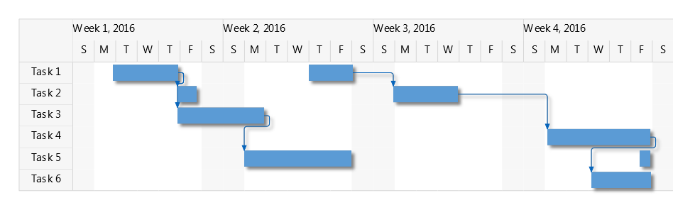
diagram.Factory
.CreateShapeNode(10, 10, 20, 20)
.Brush(Color.LightGray)
.Font("Arial", 12)
.EnableStyledText(true)
.Text("Task 1")
.ToolTip("This is the task");
new TreeLayout()
.LevelDistance(20)
.NodeDistance(20)
.LinkStyle(TreeLayoutLinkType.Cascading3)
.Arrange(diagram);
DiagramLink Improvements
- The component no longer keeps a separate segmentCount field, removing a common source of errors. The SegmentCount property now calculates its value from ControlPoints elements. The UpdateFromPoints(updateGroups, updateSegments) overload has been removed too.
- SegmentCount setter no longer refuses changing number of segments if auto-routing is enabled or the link is a self-loop.
- The new Spline element of LinkShape enumeration draws links as interpolating splines that pass through all of their control points:
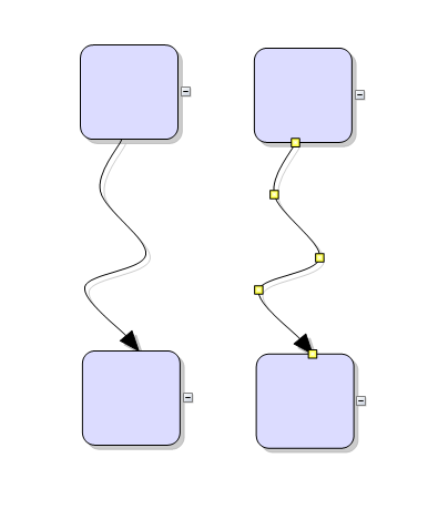
WinForms Diagram Control: Spline Links
Miscellaneous
- The ModifierKeyAction.ExtendSelection mode selects items within the lasso without deselecting old ones.
- The Visio Stencils import API provides access to BeginArrow and EndArrow values.
- The Visio Stencils import API provides access to Connection elements defined for a shape.
- It is now enough to set EnableStyledText to enable styled-text mode without having to also enable PolygonalTextLayout.
- Fixed bug where ItemAdded event wasn’t raised for interactively drawn items.
- Miscellaneous UI control assemblies (NodeListView, LayerListView, Ruler, etc) have been merged into a single MindFusion.Diagramming.WinForms.Controls.dll.
A direct link to download the trial version follows:
Download MindFusion WinForms Diagram Component, V 6.4.2
Updated assemblies are also available as MindFusion.Diagramming NuGet package.
About MindFusion.Diagramming for WinForms: A programming component that provides any WinForms application with a full set of features for creating and customizing all types of diagrams, flowcharts, schemes, hierarchies, trees, graphs etc. The control provides numerous ways to save and load a diagram, six auxiliary controls and more than 12 automatic graph layout algorithms. Diagram elements include scrollable tables, container nodes, multi-segment arrows, custom diagram item types and many more. Further details here.
Diagramming for WinForms is a royalty-free component, clients get 12 month upgrade subscription when buying a license. The source code is also available for purchase. Visit the buy page for a list with the current license prices.